
Method and Apparatus for Generating Hydrogen

Inactive Publication Date: 2007-05-24
WILSON MAHLON S
View PDF40 Cites 9 Cited by
  • Summary
  • Abstract
  • Description
  • Claims
  • Application Information

AI Technical Summary

Benefits of technology

[0019] An advantage of the present invention is that the heat source is preferably sufficiently abundant to overcome heat losses in smaller devices, thereby preferably eliminating the need for heat recovery devices.

Problems solved by technology

On the other hand, the extensive subsystems required to manage the water and heat greatly complicate the system, further compounding operational difficulties as well as cost and reliability.
Amongst such difficulties is the appreciable byproduct CO formed by the steam reforming reaction, which is a poison to low-temperature fuel cell systems.
The CO level can be lowered to ppm levels using high steam-to-methanol ratios and additional WGS and preferential oxidation reactors, resulting in an even yet more complicated system.
However, steam reforming is difficult to implement in small systems.
Scaling down the highly integrated and complicated systems discussed above is difficult and expensive.
Particularly, heat losses become much more pronounced.
Thus, additional challenges and difficulties are encountered in developing small-scale thermal process systems.
Typically, a 1:1 molar ratio (64 wt % methanol) is used per the stoichiometery of Equation 1, even though conversion is not optimal with the low steam content.
A possibly greater difficulty is the heat management, as discussed above.
To some extent it is possible to compensate for the heat losses or maximize recovery from the scant heat sources available, but the system either becomes too inefficient or too complicated to be attractive for portable applications.
However, known decomposition systems suffer from many disadvantages, including for example the higher amount of heat required to liberate hydrogen and less hydrogen produced per mole of methanol (and thus lower efficiency) relative to steam reforming, and difficulties with a high CO concentration that impedes hydrogen permeation through permselective membranes.
Further, known methanol decomposition systems do not take advantage of the high heat value of the CO produced in the hydrogen generation reaction.

Method used


Image

  • Method and Apparatus for Generating Hydrogen
  • Method and Apparatus for Generating Hydrogen
  • Method and Apparatus for Generating Hydrogen

Examples


Embodiment Construction

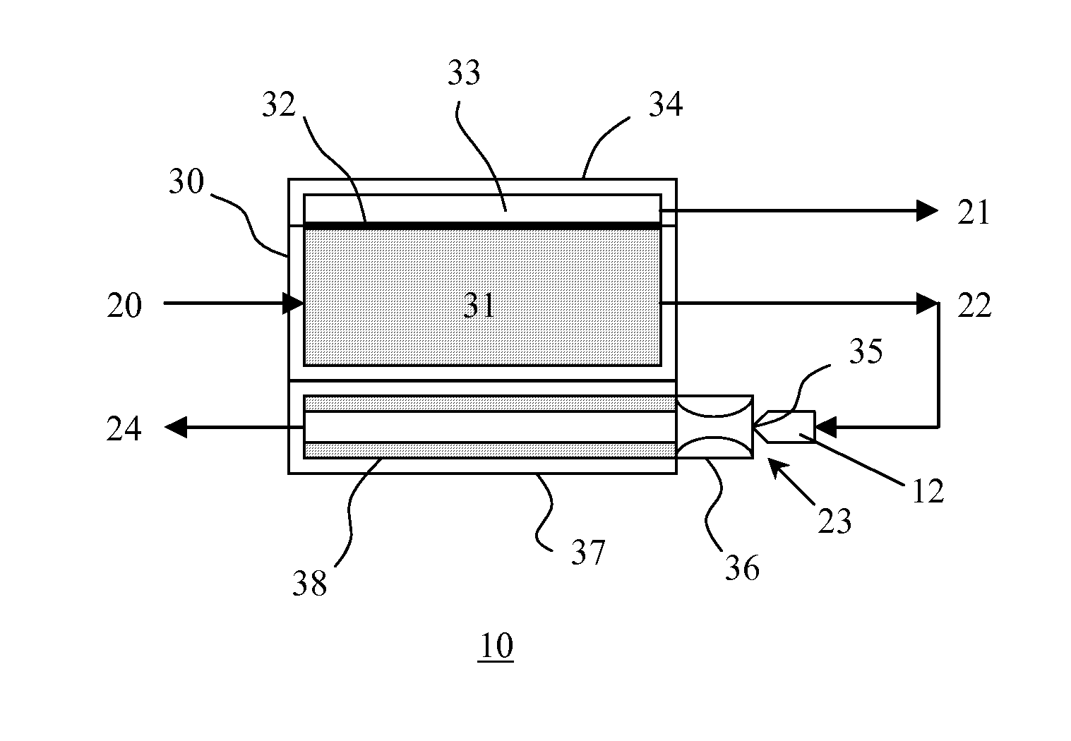
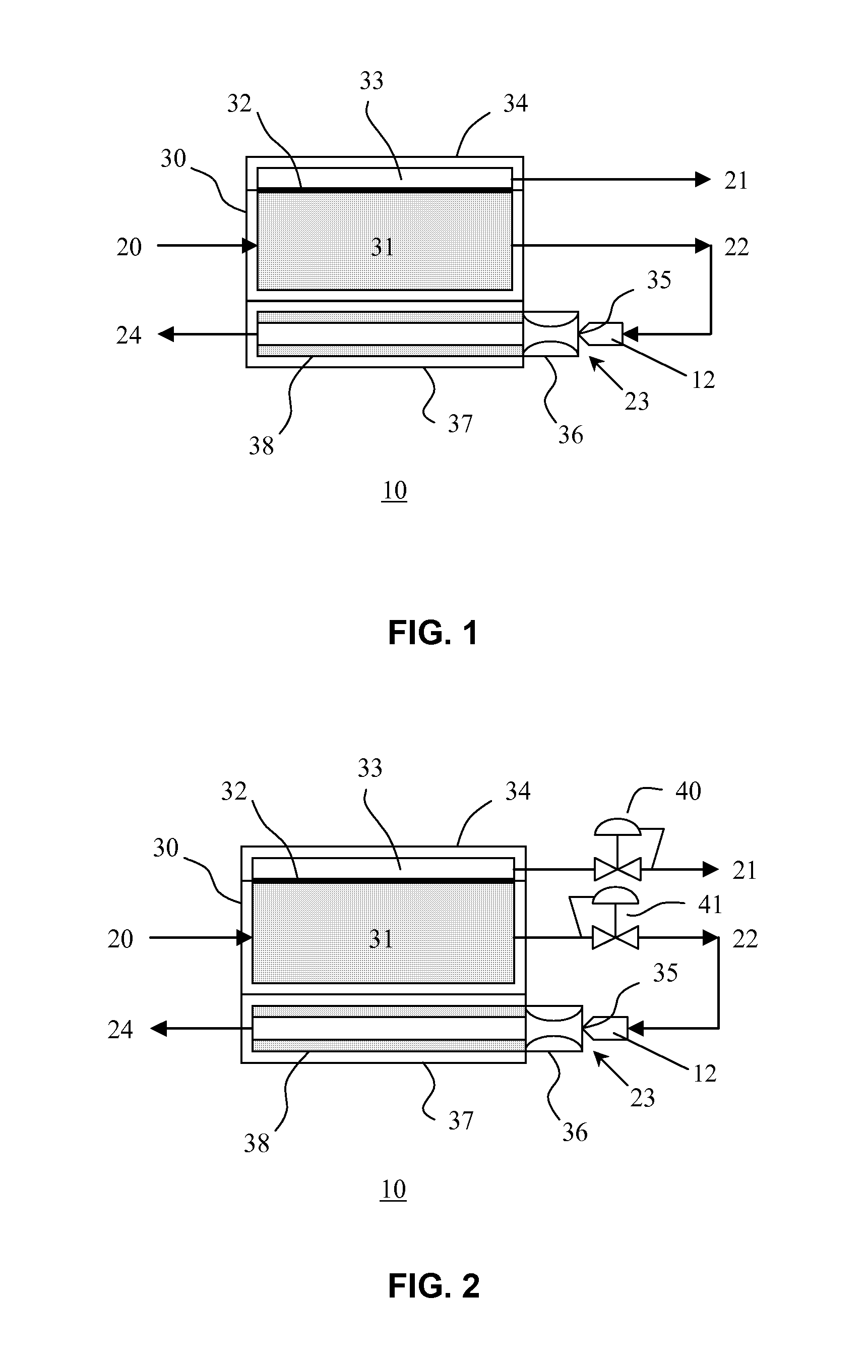
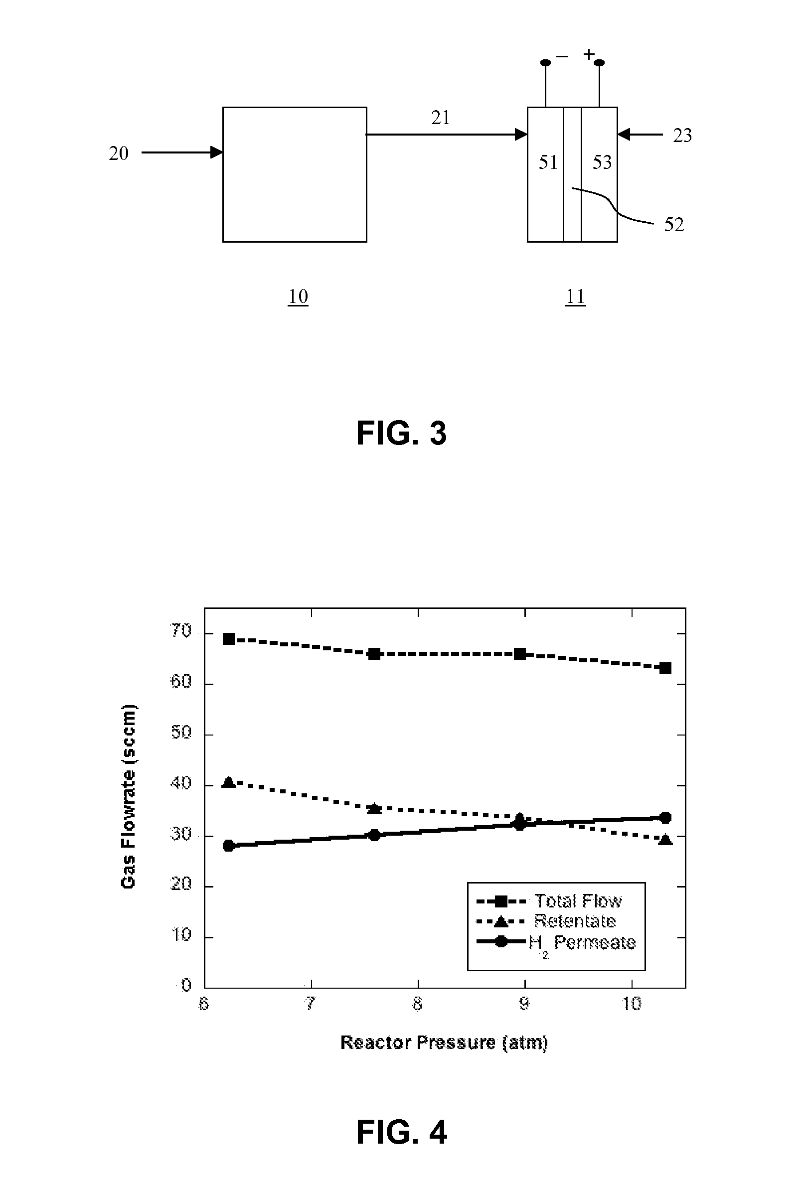
[0027] The present invention relates to a hydrogen generator that preferably comprises a reactor feed pump, a reactor feed that preferably comprises approximately 75-100 wt % methanol and 0-25 wt % water, a decomposition reactor preferably comprising a methanol decomposition selective catalyst, a hydrogen permselective separator to split the methanol decomposition products into permeate (hydrogen) and retentate (primarily CO), and a heater that burns the retentate using oxygen (air) to provide heat for the reactor and the permselective separator.

[0028] Although methanol is a preferred fuel, any endothermically decomposable compound may be used, including but not limited to carbohydrazide, It is preferable that the fuel used is relatively easy to decompose, decomposes endothermically to one or more byproducts which have high heat value, and produces little coking or other contamination of the permselective membrane.

[0029] A permselective separator is preferably used to avoid contam...


PUM


Abstract

Method and apparatus for generating hydrogen from a fuel comprising an endothermically decomposable compound, preferably methanol, and optionally comprising water. A catalyst is preferably used to decompose the methanol into hydrogen and CO. The catalyst preferably has low selectivity for reacting the CO and water to form CO2 and hydrogen. A permselective membrane, preferably cleaned by the water, is used to separate the hydrogen. The retentate has fuel value and is reacted or otherwise burned in order to provide heat for the decomposition reaction.

Description

CROSS-REFERENCE TO RELATED APPLICATIONS [0001] This application claims the benefit of the filing of U.S. Provisional Patent Application Ser. No. 60 / 739,495, entitled “Methanol Decomposition Hydrogen Generator”, filed on Nov. 23, 2005, and the specification thereof is incorporated herein by reference.BACKGROUND OF THE INVENTION [0002] 1. Field of the Invention (Technical Field) [0003] The present invention relates to a hydrogen generating apparatus, method, and system. The present invention preferably decomposes an endothermically decomposable compound. The present invention preferably uses a hydrogen permselective separator to separate methanol decomposition products into permeate (hydrogen) and retentate (primarily CO). The retentate is then fed to a heater that burns the retentate using oxygen, preferably from air, to provide heat to the reactor and / or permselective separator. [0004] 2. Description of Related Art [0005] Note that the following discussion refers to a number of publ...

Claims


Application Information

Patent Timeline
IPC IPC(8): H01M8/06B01J19/00C01B3/26
CPCB01J8/009H01M8/0687B01J19/249B01J19/26B01J2208/00309B01J2208/00504B01J2219/2453B01J2219/2458B01J2219/2459B01J2219/2466B01J2219/247B01J2219/2479B01J2219/2485B01J2219/2486C01B3/22C01B3/501C01B2203/0277C01B2203/041C01B2203/047C01B2203/066C01B2203/0811C01B2203/0822C01B2203/1064C01B2203/1223Y02E60/50H01M8/0618H01M8/04022B01J8/02Y02P20/10C01B3/26H01M8/04H01M8/06
Inventor WILSON, MAHLON S.
Owner WILSON MAHLON S
Learn More