Method of driving high definition opposed discharge plasma display panel

a plasma display panel and high-definition technology, applied in the direction of instruments, static indicating devices, etc., can solve the problems of reduced yield, large increase of process difficulty, and significant noise, and achieve the effect of effectively eliminating noise, reducing peak current and electromagnetic interference, and significantly increasing the surface area coated with phosphor

Inactive Publication Date: 2007-05-24
MARKETECH INT
View PDF2 Cites 0 Cited by
  • Summary
  • Abstract
  • Description
  • Claims
  • Application Information

AI Technical Summary

Benefits of technology

[0009] It is an object of the present invention to provide a method of driving a high definition opposed discharge PDP comprising transversely disposing a barrier rib on a center of any one of a plurality of elongate discharge cells in any one of a plurality of pixels of the opposed discharge PDP wherein the discharge cell is divided into two sub-cells by the barrier rib; disposing a sustain electrode on a front substrate corresponding to either sub-cell; causing a driving circuit to apply a sustaining pulse to each of the plurality of sustain electrodes in a sustaining period of each sub-field; and causing a phase of the sustaining pulse on the sustain electrode corresponding to one sub-cell to have a phase difference of 180 degrees relative to that of the sustaining pulse on the sustain electrode corresponding to the other adjacent sub-cell. By utilizing this method, discharge direction of the sub-cell corresponding to odd number pixel is opposite to that of the sub-cell corresponding to even number pixel in order to effectively eliminate noise caused by vibration of the opposed discharge PDP in discharge. Moreover, a reduction of peak current and electromagnetic interference is made possible. In addition, area coated with phosphor is significantly increased because the discharge cell is divided into two sub-cells. As a result, both light emitting efficiency and brightness of the opposed discharge PDP are greatly increased, and thus image with high quality is shown.
[0010] One aspect of the present invention the method comprises causing a driving circuit to apply a sustaining pulse to each of the plurality of sustain electrodes; and causing a phase of the sustaining pulse on the sustain electrode corresponding to one sub-cell to have a phase difference of 180 degrees relative to that of the sustaining pulse on the sustain electrode corresponding to the other adjacent sub-cell. By utilizing this method, discharge directions of two adjacent sub-cells of the discharge cell are opposite in order to substantially eliminate noise caused by vibration of the opposed discharge PDP in discharge due to opposite vibration directions.

Problems solved by technology

As a result, noise is significantly serious.
However, such strict control results in a great increase of process difficulty and a decreased yield.
This can greatly decrease light emitting efficiency of phosphor coated on distal ends relative to the center of the discharge cell 13.
As a result, the total light emitting efficiency is very low.

Method used


Image

  • Method of driving high definition opposed discharge plasma display panel
  • Method of driving high definition opposed discharge plasma display panel
  • Method of driving high definition opposed discharge plasma display panel

Examples


Embodiment Construction

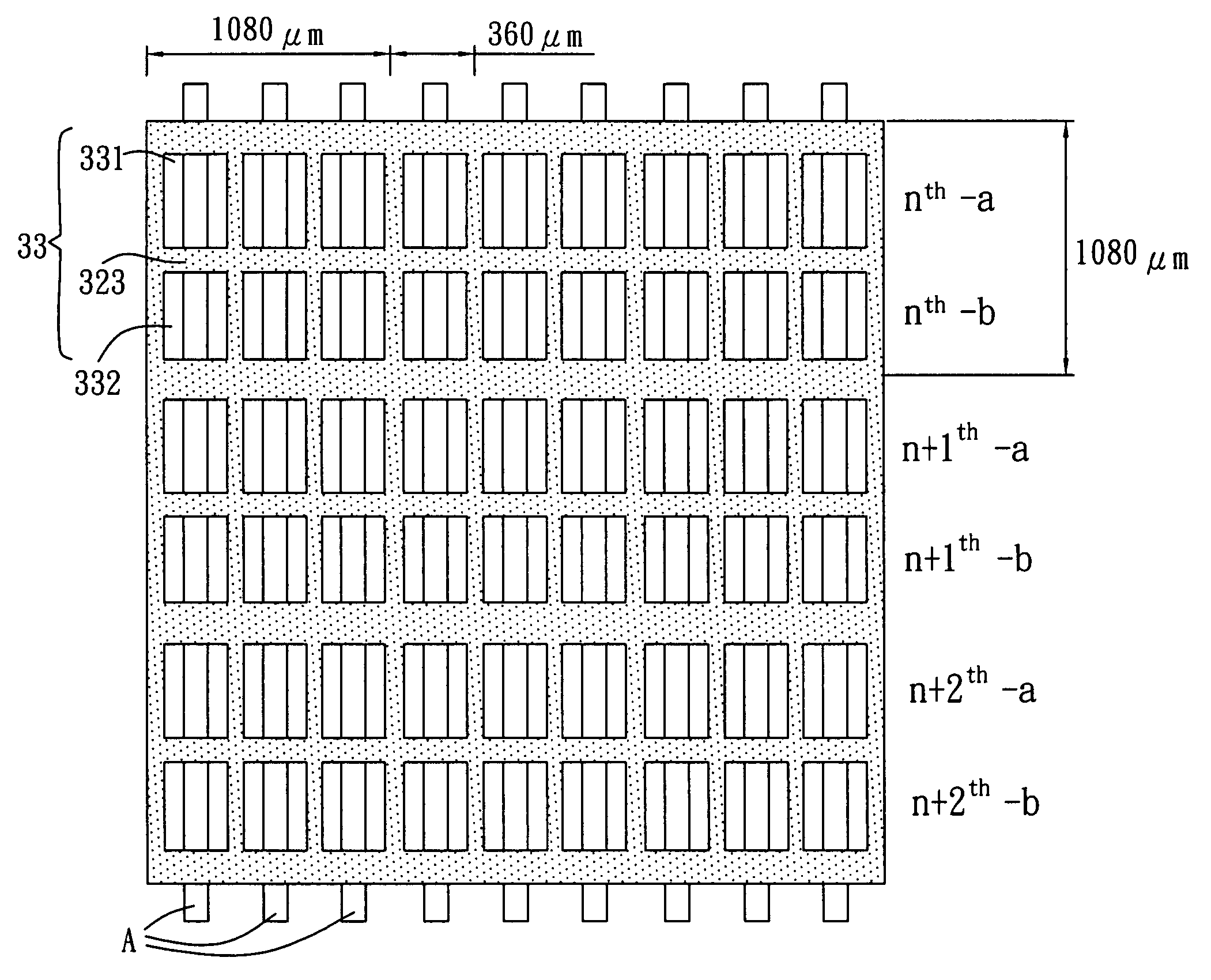
[0029] The invention is directed to a method of driving a high definition opposed discharge plasma display panel (PDP) comprising transversely disposing a barrier rib on a center of any elongate discharge cell in any pixel of the opposed discharge PDP wherein the discharge cell is divided into two sub-cells by the barrier rib; disposing a sustain electrode on a front substrate corresponding to either sub-cell; causing a driving circuit to apply a sustaining pulse to each of the plurality of sustain electrodes in a sustaining period of each sub-field; and causing a phase of the sustaining pulse on the sustain electrode corresponding to one sub-cell to have a phase difference of 180 degrees relative to that of the sustaining pulse on the sustain electrode corresponding to the other adjacent sub-cell such that two adjacent sub-cells may discharge in opposite directions. Alternatively, the method comprises causing a phase of the sustaining pulse on the sustain electrode corresponding to...


PUM


Abstract

The present invention is to provide a method of driving a high definition opposed discharge PDP comprising transversely disposing a barrier rib on a center of any elongate discharge cells of the opposed discharge PDP to divide the discharge cell into two sub-cells; disposing a sustain electrode on a front substrate corresponding to either sub-cell; causing a driving circuit to apply a sustaining pulse to each of the plurality of sustain electrodes in a sustaining period of each sub-field; and causing a phase of the sustaining pulse on the sustain electrode corresponding to one sub-cell to have a phase difference of 180 degrees relative to that of the sustaining pulse on the sustain electrode corresponding to the other adjacent sub-cell in order to effectively eliminate noise caused by vibration of the opposed discharge PDP in discharge, reducing peak current and electromagnetic interference, and greatly increase both light emitting efficiency and brightness of the opposed discharge PDP.

Description

FIELD OF THE INVENTION [0001] The present invention relates to opposed discharge plasma display panels (PDPs), and more particularly to a method of driving a high definition opposed discharge PDP in order to effectively eliminate noise caused by vibration of the opposed discharge PDP in discharge and greatly increase both light emitting efficiency and brightness of the opposed discharge PDP. BACKGROUND OF THE INVENTION [0002] A method of manufacturing a conventional opposed alternating current discharge (i.e., AC type) PDP 10 is illustrated in FIG. 1, wherein two different layers are formed on two opposed glass substrates 11 and 12, the peripheries of the glass substrates 11 and 12 are sealed together to form a space between the two glass substrates, specific gas (e.g., helium (He), neon (Ne), xenon (Xe), or argon (Ar)) is mixed in a predetermined ratio and is filled in discharge cells 13 formed within the space between the two glass substrates 11 and 12. The substrate facing a view...

Claims


Application Information

Patent Timeline
Patent Type & Authority Applications(United States)
IPC IPC(8): G09G3/28
CPCG09G3/297G09G2330/025G09G2330/06
Inventor KAO, HSU-PINLIANG, JANG-JENGTSAI, TSAN-HUNGHSU, SHENG-WENKAO, HSU-CHIA
Owner MARKETECH INT
Why Eureka
Try Eureka