Braking system for vehicle
a technology for braking systems and vehicles, applied in braking systems, positive displacement liquid engines, liquid fuel engines, etc., can solve problems such as noise generation, and achieve the effect of high mechanical strength of pistons
- Summary
- Abstract
- Description
- Claims
- Application Information
AI Technical Summary
Benefits of technology
Problems solved by technology
Method used
Image

Examples
first embodiment
[0022] A first embodiment of the present invention will be explained with reference to the drawings of FIGS. 1 to 3.
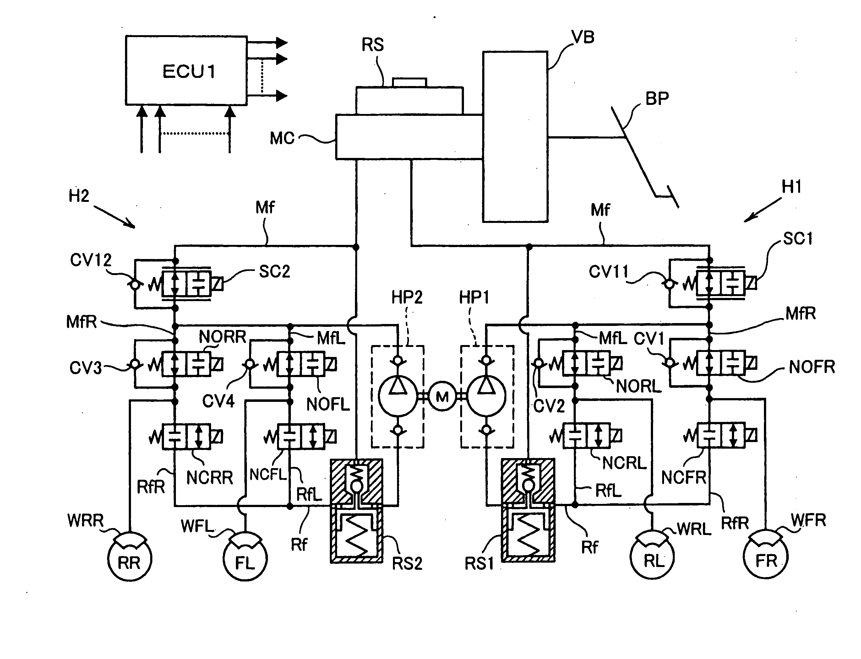
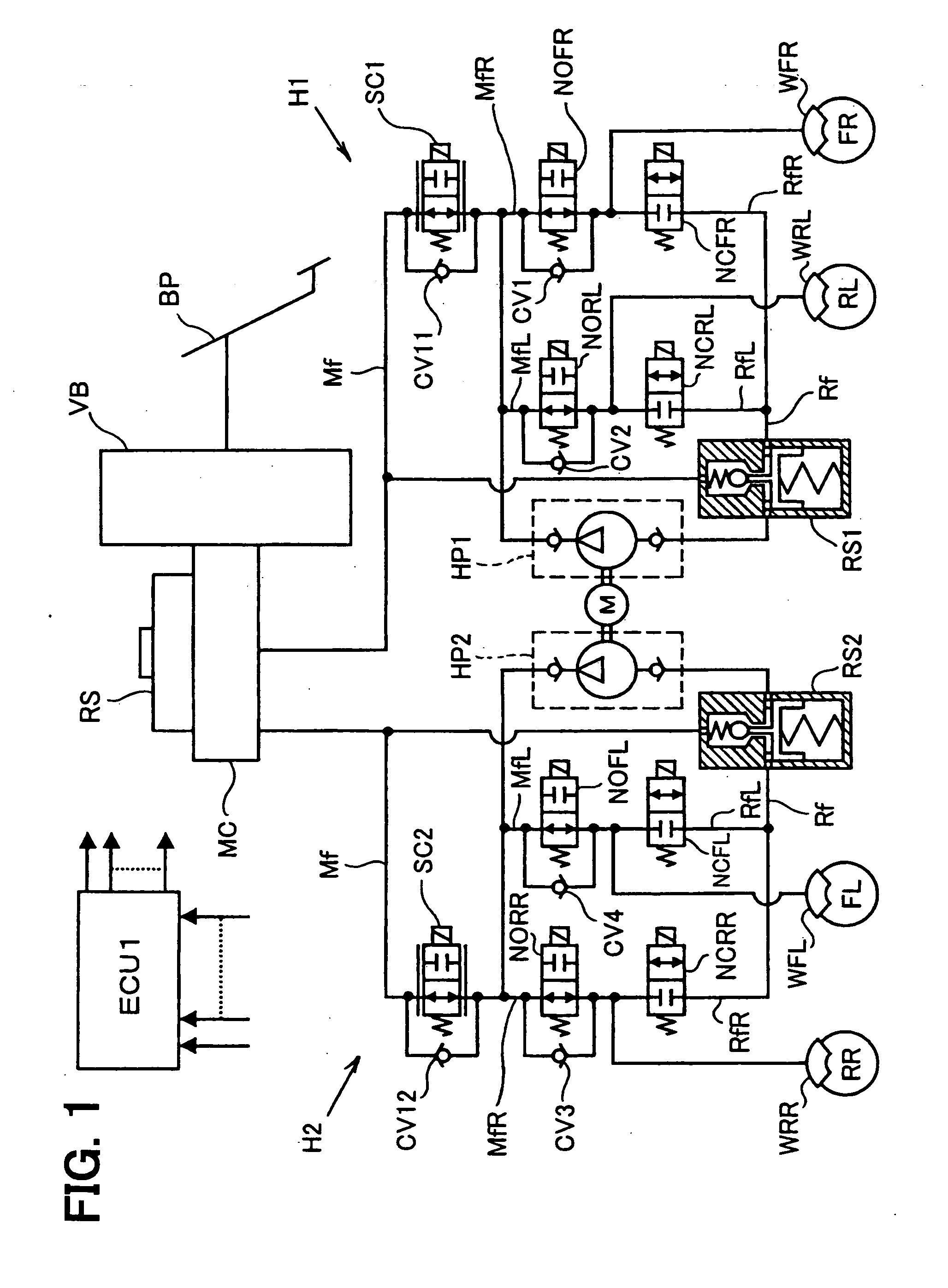
[0023] In a braking system for a vehicle according to the embodiment of the present invention, as shown in FIG. 1, a brake pedal BP for performing a braking operation of the vehicle is operatively linked with a master cylinder MC of a well known tandem type, via also well known vacuum booster VB. A pair of pressure generating chambers (not shown) is formed in the master cylinder MC, wherein the pressure generating chambers are arranged at right and left hand sides of the master cylinder MC in FIG. 1. When the brake pedal BP is operated, the respective pressure generating chambers are blocked off from a main reservoir RS, pressure of which is maintained at atmospheric pressure. And fluid pressure is generated at the respective pressure generating chambers, corresponding to a braking force applied to the brake pedal BP.
[0024] The pressure generating chamber of the mast...
second embodiment
[0078] A second embodiment is shown in FIG. 4. The same reference numerals are used in the second embodiment for designating the same or similar parts to the first embodiment.
[0079] An air communication aperture 84 is provided in the first housing member 10, so that a volume changing chamber 82 (which corresponds to the sealed chamber 52 in FIG. 3) is opened to the atmospheric air. In the first embodiment, the sealed chamber 52 is isolated from the atmospheric air. As a result, the driving force for the piston 36 must be designed to be larger in order to overcome the reaction force caused by the expansion or contraction of the fluid in the sealed chamber 52. According to the second embodiment, however, the reaction force (the resistive force) for driving the piston 36 can be reduced, because the volume changing chamber 82 is communicated with the atmospheric air. Although not shown in FIG. 4, the other end of the air communication aperture 84 may be opened to the ambient air, or ma...
third embodiment
[0081] A third embodiment is shown in FIGS. 5 and 6. The same reference numerals are likewise used in the third embodiment for designating the same or similar parts to the first embodiment.
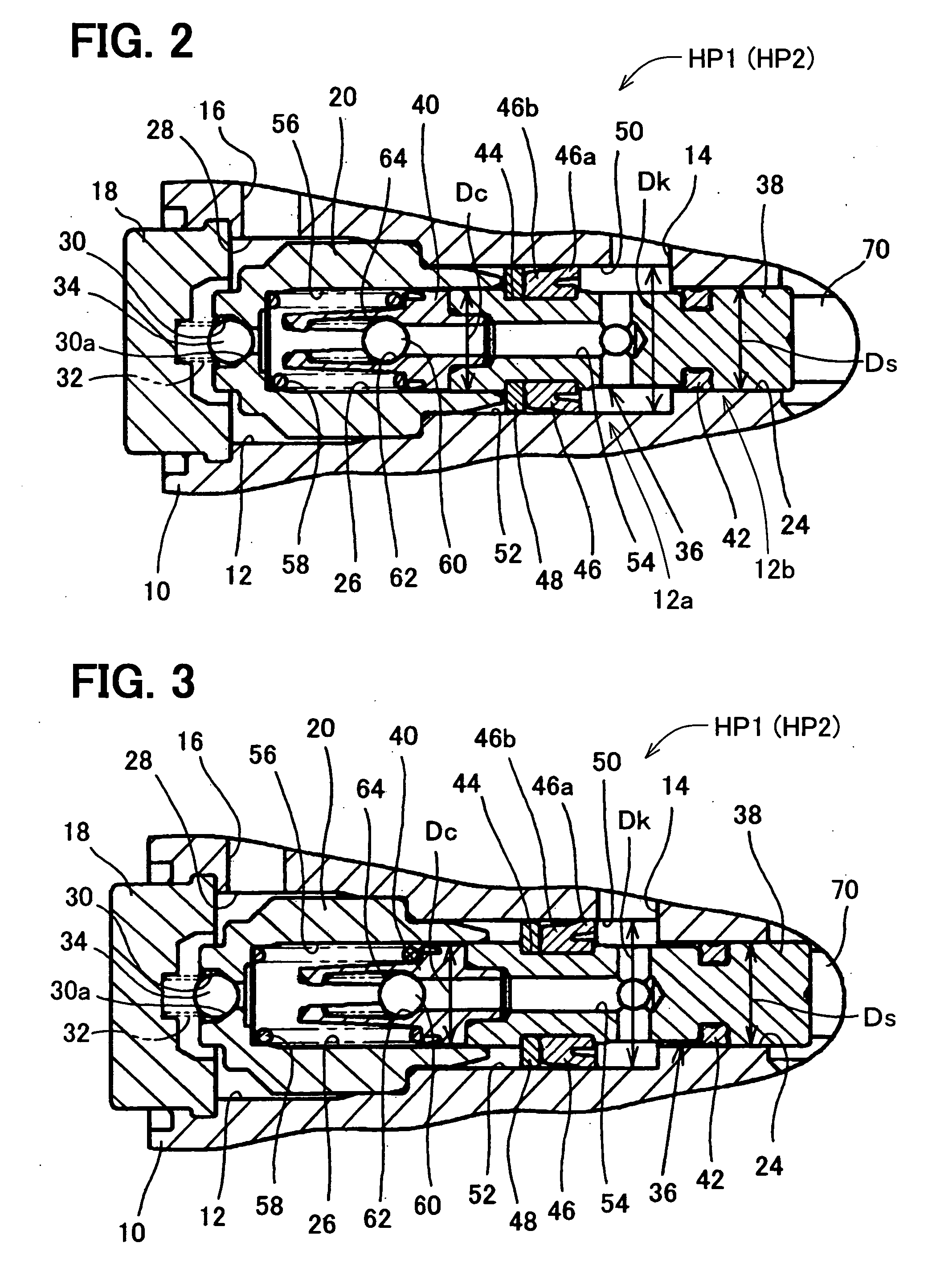
[0082] As shown in FIGS. 5 and 6, the inner diameter “Ds” of supporting hole 24 may be made smaller than the inner diameter “Dc” of the cylindrical space 26. The supporting portion 38 of the piston 36 is made smaller to the extent that the mechanical strength of the supporting portion 38 may not cause any problem, in accordance with the small-sized inner diameter of the supporting hole 24.
[0083] According to such modification, the parts for forming the suction chamber 50 can be made smaller, while the suction volume is not decreased. As a result, the liquid pump HP1, HP2 can be made smaller, compared with the liquid pump in which the inner diameter “Ds” of the supporting hole 24 is equal to or larger than the inner diameter “Dc” of the cylindrical space 26.
[0084]FIG. 5 shows the position of the...
PUM
 Abstract
Description
Claims
Application Information
 - R&D
- Intellectual Property
- Life Sciences
- Materials
- Tech Scout
- Unparalleled Data Quality
- Higher Quality Content
- 60% Fewer Hallucinations
Browse by: Latest US Patents, China's latest patents, Technical Efficacy Thesaurus, Application Domain, Technology Topic, Popular Technical Reports.
© 2025 PatSnap. All rights reserved.Legal|Privacy policy|Modern Slavery Act Transparency Statement|Sitemap|About US| Contact US: help@patsnap.com