Light-condensing head and storage apparatus

a technology which is applied in the field of light-condensing head and storage apparatus, can solve the problems of insufficient light intensity (the magnitude of electric field vectors) of the near-field light produced, and the inability to produce near-field light with augmented light intensity

Inactive Publication Date: 2007-05-17
KONICA MINOLTA INC
View PDF4 Cites 15 Cited by
  • Summary
  • Abstract
  • Description
  • Claims
  • Application Information

AI Technical Summary

Benefits of technology

[0026] In view of the conventionally experienced disadvantages and inconveniences discussed above, it is an object of the present invention to provide a light-condensing head or the like that can efficiently produce near-field light with augmented light intensity.

Problems solved by technology

Here, SPP produced by the periodic surface irregularities interferes with radically polarized beam to produce an intense electric field.
With smaller openings, however, it is difficult to produce near-field light with augmented light intensity; that is, it is impossible to sufficiently augment the light intensity (the magnitude of the electric field vectors) of the near-field light produced.
However, just as described above, with smaller openings, it is difficult to produce near-field light with augmented light intensity.
Light polarized in such a special direction, however, is extremely difficult to produce.
Such coincidence, however, is extremely difficult to achieve.
Thus, it can be said that, with the light-condensing technology disclosed in Patent Document 3, it is difficult to easily produce a radially polarized beam, which is the prerequisite for producing near-field light.
Moreover, it is also extremely difficult to fabricate the combined polarization rotator 105′ incorporating a plurality of types of polarization rotator 105, its fabrication requiring high cost.
Inconveniently, however, localized plasmon is produced only by P-polarized light, and this property makes it difficult for the light-condensing technology disclosed in Patent Document 4 to efficiently produce near-field light with augmented light intensity.
Hence, it can be said that the light-condensing technology disclosed in Patent Document 4 does produce near-field light with augmented light intensity but with poor efficiency.

Method used


Image

  • Light-condensing head and storage apparatus
  • Light-condensing head and storage apparatus
  • Light-condensing head and storage apparatus

Examples


embodiment 1

[0122] An embodiment of the present invention will be described below with reference to the drawings. It should be noted that, in the following description, radially polarized waves are indicated as “R” some times but not at other times, in which latter case it is to be understood that reference to another drawing is requested.

1. Construction of a Storage Apparatus

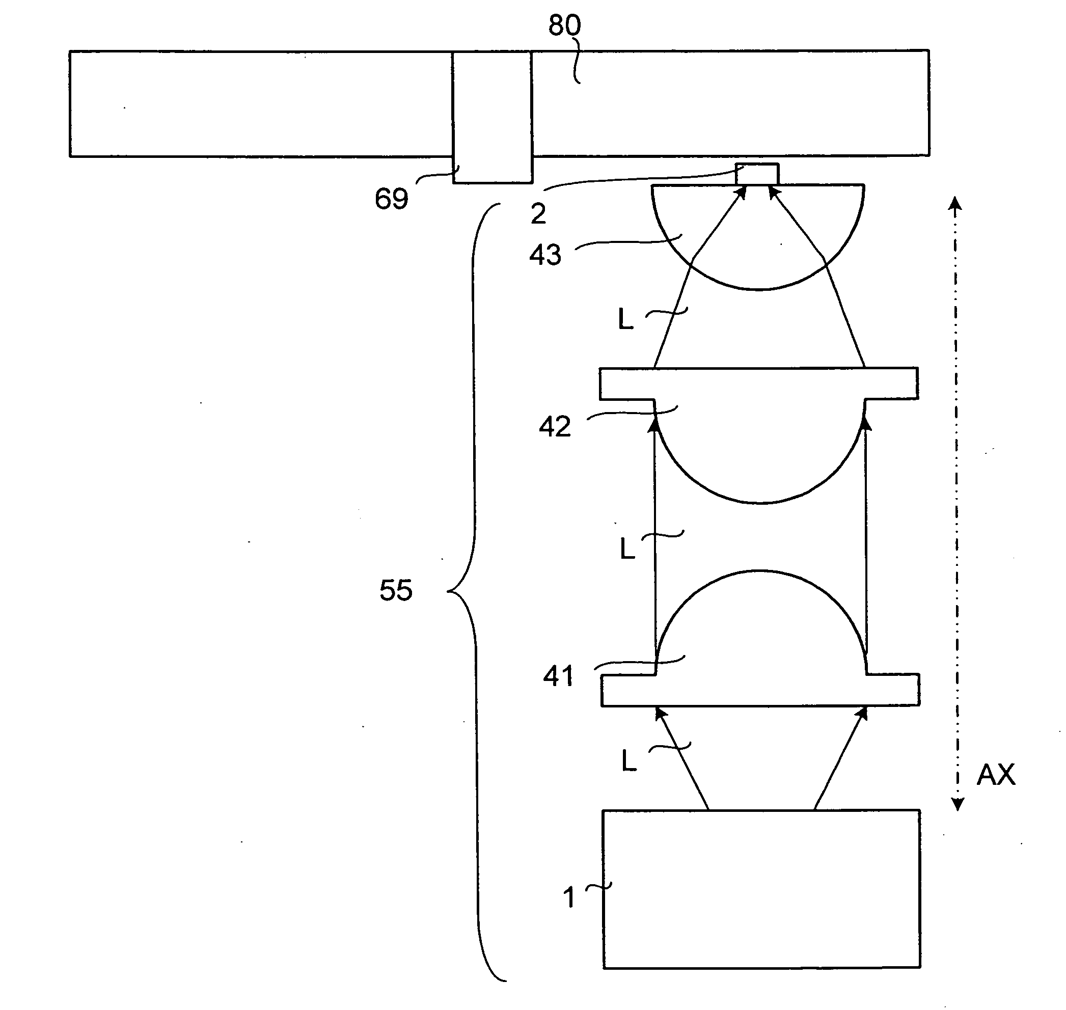
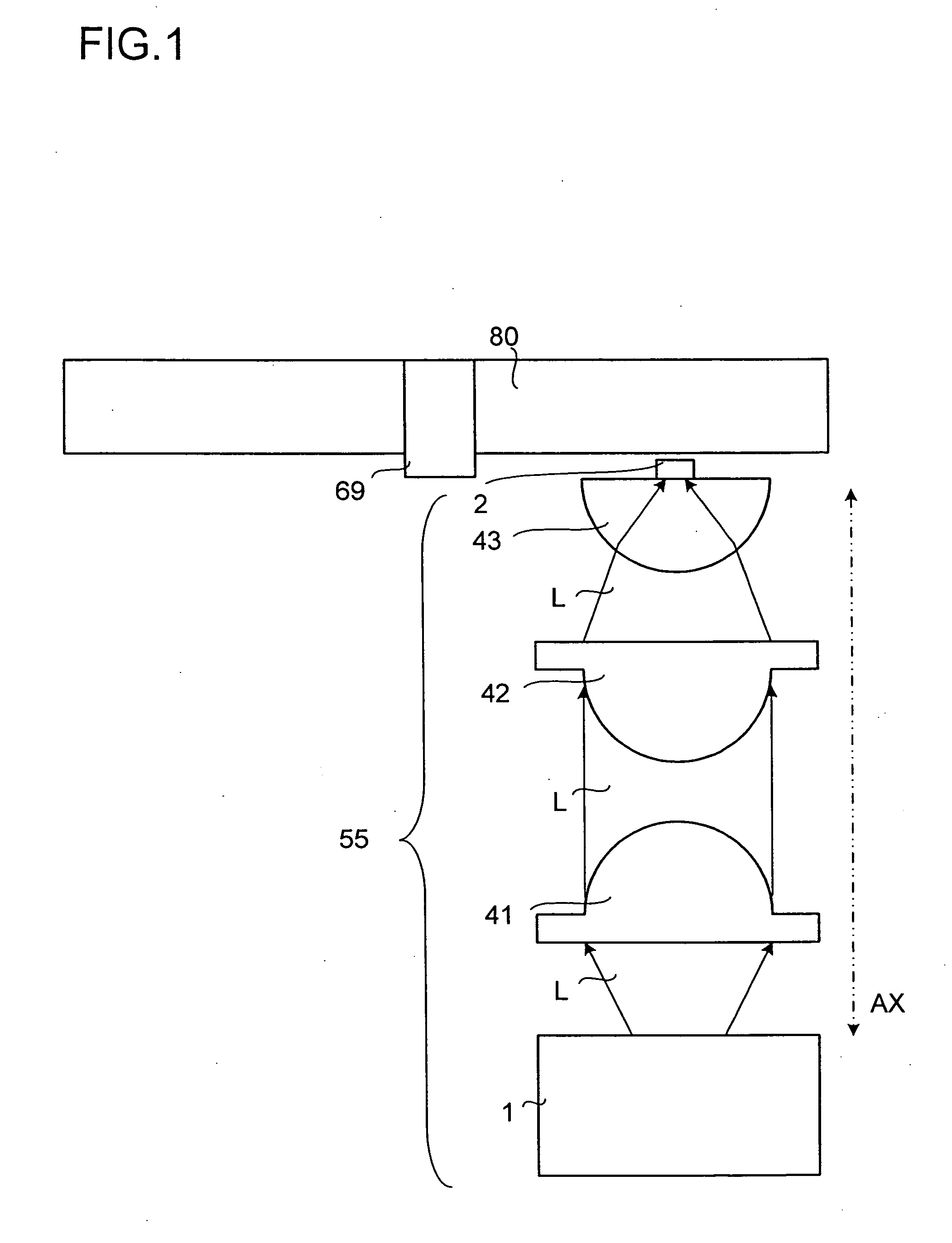
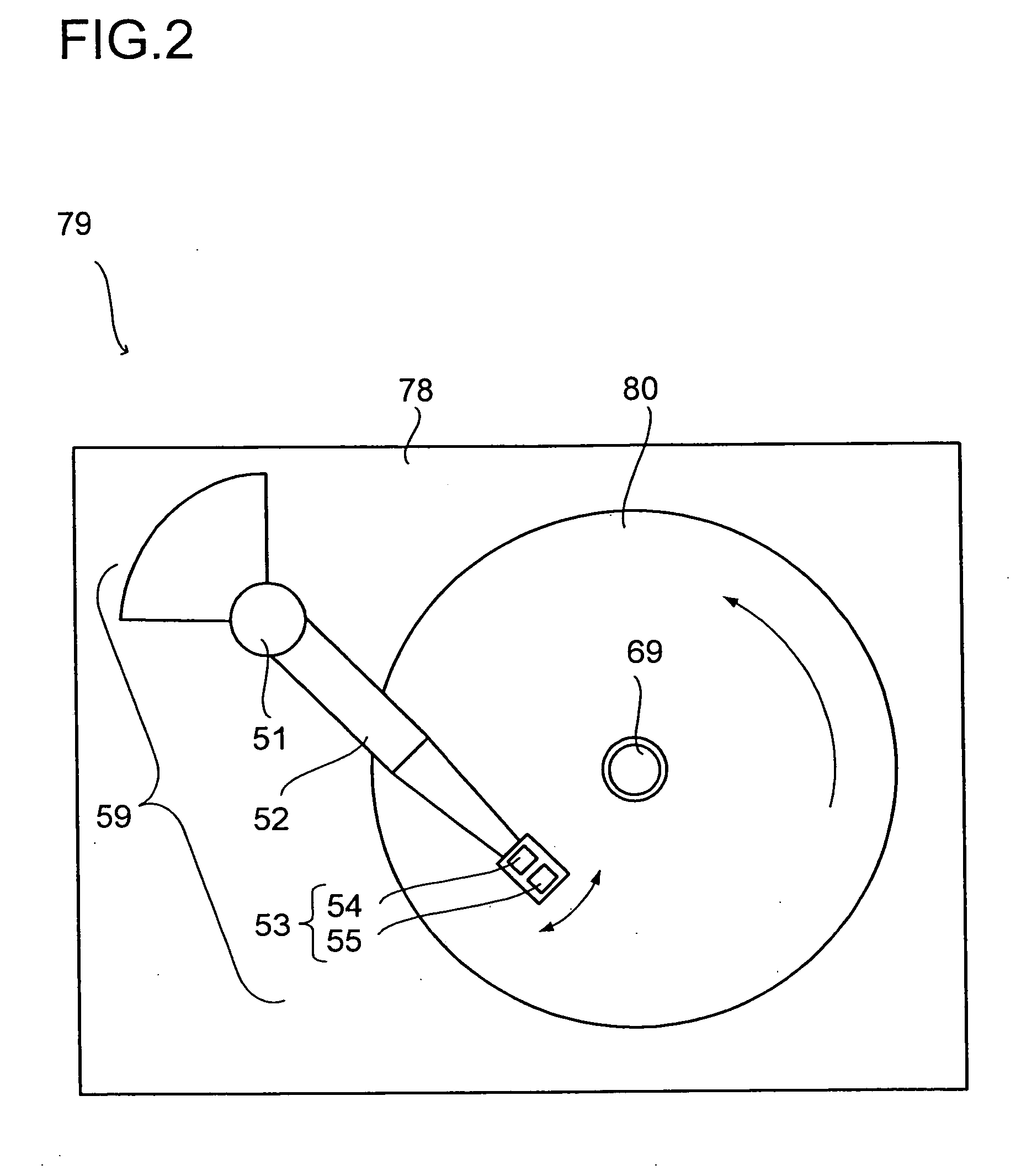
[0123]FIG. 2 is a diagram schematically showing the construction of a HDD 79 adopting heat-assisted magnetic recording, as an example of a storage apparatus. As shown in the figure, the HDD 79 includes, housed inside a housing 78: a spindle motor 69 that holds and rotates a magnetic recording medium (disk) 80; and an actuator assembly 59.

[0124] The actuator assembly 59 has an actuator arm 52 that is rotatable on a pivot (rotary shaft) 51. At the non-pivoted end of the actuator arm 52, a head unit 53 is fitted.

[0125] The head unit 53 includes: a magnetic head 54 that writes and reads magnetic information to and from th...

embodiment 2

[0281] A second embodiment of the present invention will be described below. Such members as are used or find their counterparts in the first embodiment will be identified with common reference numerals and symbols, and no explanations thereof will be repeated.

[0282] In the first embodiment, the light source unit 1 includes a half-wave plate 4 to make light contain more radially polarized waves R. The present invention, however, is not limited to such a design. For example, the light source unit 1 may instead include a polarization rotator (a scheme that employs a polarization rotator is called Scheme 4).

[0283] Scheme 4

[0284] A polarization rotator rotates the direction of the electric field vectors of light (its polarization direction). FIGS. 37A and 37B show how a polarization rotator 5 changes an electric field vector. The symbol “&” denotes that light with electric field vectors as indicated by an arrow with a hollow inside is passed through a polarization rotator 5 with a ro...

embodiment 3

[0290] A third embodiment of the present invention will be described below. Such members as are used or find their counterparts in the first and second embodiments will be identified with common reference numerals and symbols, and no explanations thereof will be repeated.

[0291] In the first and second embodiments, the light emitted from the 2-D PCL 3 is passed trough a half-wave plate 4 or through a polarization rotator 5 so as to contain more radially polarized waves R. The present invention, however, is not limited to such a design. For example, the light emitted from the 2-D PCL 3 may itself contain radially polarized waves R.

[0292] Specifically, the TM oscillation mode of the 2-D PCL 3 is exploited. Normally, a semiconductor laser has TE oscillation mode (TE mode) and TM oscillation mode (TM mode). Accordingly, as shown in FIG. 40, the 2-D PCL 3 has TE oscillation mode, in which it produces an electric field E parallel to and a magnetic field H perpendicular to the layer surfa...


PUM

PropertyMeasurementUnit
azimuth angleaaaaaaaaaa
diametersaaaaaaaaaa
wavelengthaaaaaaaaaa

Abstract

A light-condensing head has a light source unit, a light-condensing element that condenses the light emitted from the light source unit, and an electrically conductive scatterer that, when irradiated with light, produces localized plasmon at the light condensation position of the light from the light-condensing element. The light emitted from the light source unit contains, at least in part thereof, polarized waves that constitute a rotation-symmetric radiating electric field vector distribution in which the electric field vectors have equal magnitudes at equal distances from the center of rotation symmetry. The electrically conductive scatterer has, in the light-receiving portion thereof that receives the light from the light-condensing element, rotation symmetry of order three or more.

Description

[0001] This application is based on Japanese Patent Application No. 2005-332895 filed on Nov. 17, 2005, the contents of which are hereby incorporated by reference. BACKGROUND OF THE INVENTION [0002] 1. Field of the Invention [0003] The present invention relates to a light-condensing head capable of producing near-field light, and also relates to a storage apparatus provided therewith. [0004] 2. Description of Related Art [0005] In recent years, to achieve higher recording densities in magnetic disk apparatuses (e.g., hard disk drives, abbreviated to HDDs), there have been developed various types of heat-assisted magnetic recording that exploits temperature-dependence of magnetization. According to this recording method, a very small light spot is shone on a magnetic medium and thereby the temperature of the irradiated part is instantaneously raised so that recording is achieved by a drop in coercivity resulting from the raise in temperature. On completion of recording, the recorded ...

Claims


Application Information

Patent Timeline
Patent Type & Authority Applications(United States)
IPC IPC(8): G11B11/00
CPCG11B5/09G11B2005/001G11B2005/0021
Inventor YOKOYAMA, MITSURUKONNO, KENJI
Owner KONICA MINOLTA INC
Why Eureka
Try Eureka