Branch tee fitting

a brazing tee and fitting technology, applied in branching pipes, other domestic objects, mechanical instruments, etc., can solve the problems of high fabrication cost and other problems, and achieve the effects of stabilizing the brazing quality, enhancing the brazing strength, and being sufficiently usabl

Inactive Publication Date: 2007-05-10
DAIKIN IND LTD
View PDF7 Cites 1 Cited by
  • Summary
  • Abstract
  • Description
  • Claims
  • Application Information

AI Technical Summary

Benefits of technology

[0024] With the first invention described above, the branch tee fitting is provided with the engaging pawls (14) for engaging the superposed flat portions (13), which resists spring back after press forming to keep the gap between the joint faces of the flat portions minimum and uniform. Therefore, during brazing, a solder material flows into the gap and solidifies uniformly. This stabilizes the brazing quality and enhances the brazing strength. Thus, the resulting fitting is sufficiently usable even in the case where pipes (P) for flowing a high-pressure coolant are connected thereto in a refrigerant piping system.
[0025] Moreover, each of the engaging pawls (14) engages the flat portions (13) to prevent deformation of the fitting even though one pipe (P) at a time is brazed to the fitting. This enables separate connection of three pipes (P). Furthermore, similarly to the conventional technique, the three pipes can also be brazed to this fitting by one operation. Consequently, with the present invention, the brazing workability can be enhanced.
[0026] With the second invention described above, each of the engaging pawls (14) can be formed on one of the superposed flat portions (13) to prevent spring back after press forming. Therefore, it is unnecessary to form the engaging pawls (14) on both of the flat portions (13). This simplifies the structure of the branch tee fitting.
[0027] With the third invention described above, each of the flat portions (13) is formed in a substantially triangular region defined by the base end of the tubular branch portion (12) and the edge side which is a straight line connecting associated corner points of the tubular body portion (11) and the tubular branch portion (12), whereby the engaging pawls (14) can be formed in triangular regions of the plate (1a) which have been located outside the flat portions (13) before the press forming. Therefore, the plate (1a) including the engaging pawls (14) can be obtained by cutting a rectangular material plate with efficiency. This eliminates material waste and increase in cost.
[0028] With the fourth invention described above, the engaging pawl (14) engages the superposed flat portions (13) at the center of the edge sides of the flat portions (13), whereby the flat portions (13) can be held stably. This brings the brazing stabilization, and in addition enhancement of the brazing strength can be expected.
[0029] With the fifth invention described above, each of the engaging pawls (14) is formed on a triangular region almost similar to the shape of the flat portion (13), whereby almost the entire surfaces of the flat portions (13) are held extremely stably. Therefore, further stabilization of brazing and further enhancement of the brazing strength can be expected.

Problems solved by technology

However, the branch tee fittings thus fabricated bring high fabrication costs and other problems.

Method used


Image

  • Branch tee fitting
  • Branch tee fitting
  • Branch tee fitting

Examples


Embodiment Construction

[0049] Hereinafter, embodiments of the present invention will be described in detail based on the accompanying drawings.

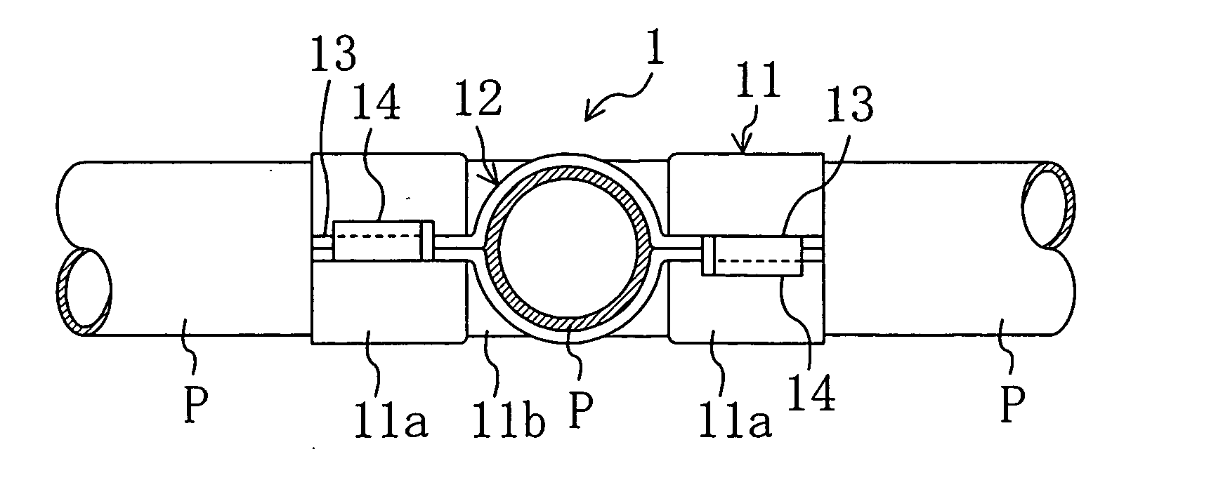
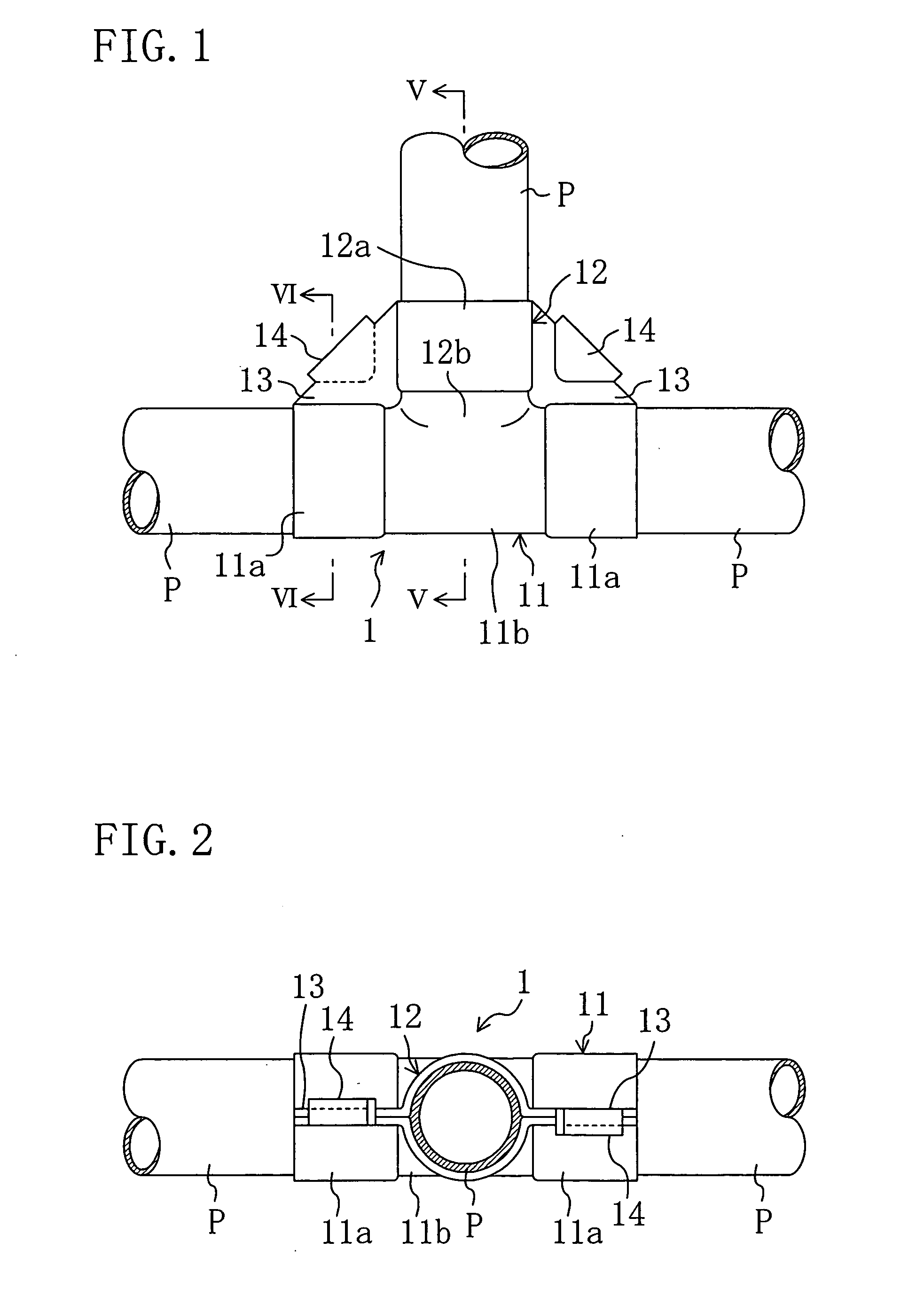
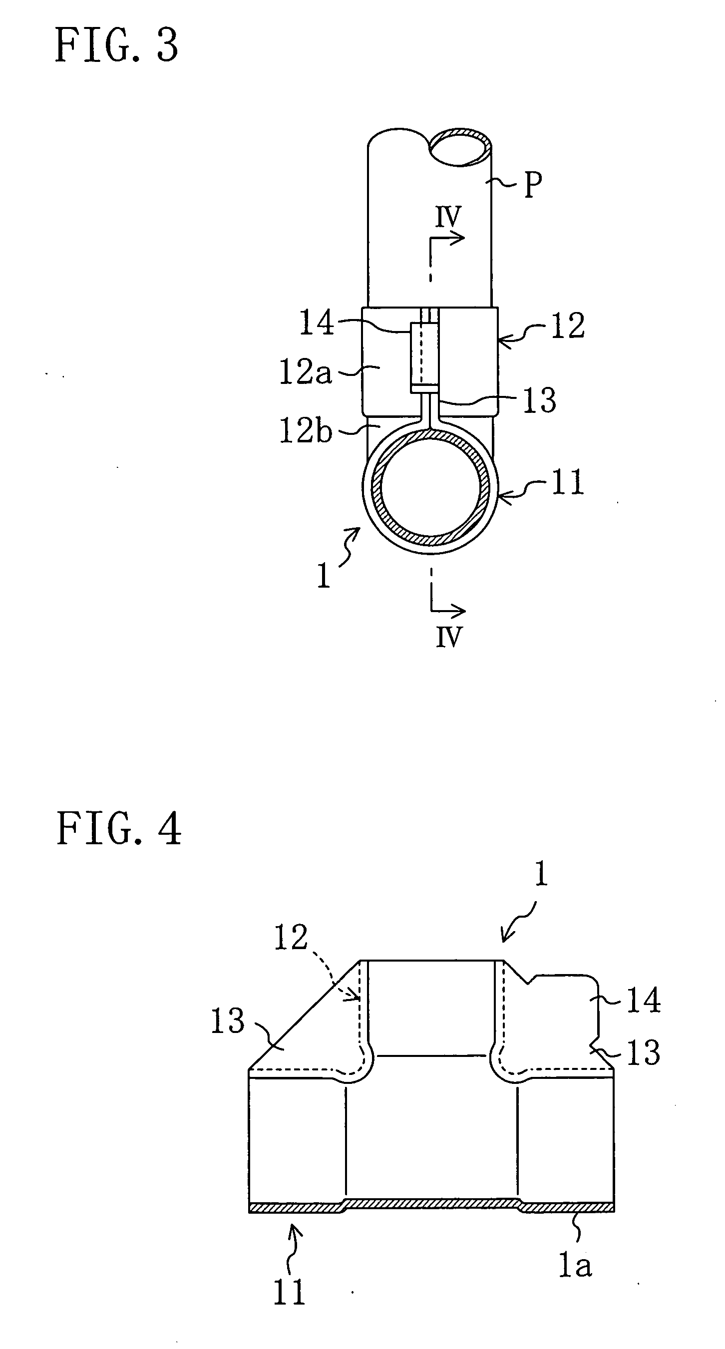
[0050]FIG. 1 is a front view of a branch tee fitting according to this embodiment in the state in which pipes (P) are joined thereto. FIGS. 2 and 3 are a plan view and a right side view of the fitting, respectively. FIG. 4 is a sectional view showing main parts of the branch tee fitting (which corresponds to a sectional view taken along the line IV-IV in FIG. 3), FIG. 5 is a sectional view of the fitting taken along the line V-V in FIG. 1, and FIG. 6 is a sectional view of the fitting taken along the line VI-VI in FIG. 1.

[0051] As illustrated in these figures, the branch tee fitting (1) includes: a tubular body portion (11) having a pair of openings at both ends; and a tubular branch portion (12) perpendicular to the tubular body portion (11). In the branch tee fitting (1), the cross section taken perpendicularly to the center line of the tubular body portion (11...


PUM

PropertyMeasurementUnit
widthaaaaaaaaaa
diameteraaaaaaaaaa
diametersaaaaaaaaaa

Abstract

In a branch tee fitting (1) fabricated by press forming, in order to enhance the brazing strength thereof and the brazing workability thereof by allowing separate brazing of pipes (P) to a tubular body portion (11) and a tubular branch portion (12), engaging pawls (14) are provided which engage flat portions (13) superposed to each other in angles between the tubular body portion (11) and the tubular branch portion (12).

Description

TECHINICAL FIELD [0001] The present invention relates to branch tee fittings, and in particular to branch tee fittings fabricated by press forming. BACKGROUND ART [0002] Conventionally, branch tee fittings for piping have typically been fabricated by bulge forming using lead. However, the branch tee fittings thus fabricated bring high fabrication costs and other problems. [0003] To solve such problems, a branch tee fitting is proposed which can be fabricated by subjecting a plate such as a copper plate to press forming (see, for example, Patent Document 1: Japanese Patent No. 2660427). This branch tee fitting is shown in FIGS. 8(A) to 8(C). FIGS. 8(A) and 8(B) are front and side views of a branch tee fitting (100), respectively, and FIG. 8(C) is a vertical mid-sectional view of the fitting shown in FIG. 8(A). [0004] The branch tee fitting (100) includes: a tubular body portion (101) having a pair of openings at both ends; and a tubular branch portion (102) perpendicular to the tubul...

Claims


Application Information

Patent Timeline
Patent Type & Authority Applications(United States)
IPC IPC(8): F16L41/00B21D39/02B21D51/16F16L41/02
CPCF16L41/021F16L41/02B21D51/16B21D39/02
Inventor NISHINO, HISANORI
Owner DAIKIN IND LTD
Why Eureka
Try Eureka