
Sheet processing apparatus and image forming apparatus including the sheet processing apparatus

a technology of image forming apparatus and processing apparatus, which is applied in the direction of electrographic process, instruments, transportation and packaging, etc., can solve the problems of sheet to stand by, sheet of the next job cannot be stacked on the processing tray, and productivity decline, so as to improve productivity and improve the return alignment property. , the effect of improving productivity

Active Publication Date: 2007-05-10
COPYER +1
View PDF3 Cites 8 Cited by
  • Summary
  • Abstract
  • Description
  • Claims
  • Application Information

AI Technical Summary

Benefits of technology

[0016] It is an object of the present invention to provide a sheet processing apparatus with increased sheet processing efficiency.
[0017] It is another object of the present invention to provide an image forming apparatus which includes the sheet processing apparatus with increased sheet processing efficiency to increase image processing efficiency.
[0023] The sheet processing apparatus of the present invention is adapted not to apply an alignment action to a sheet to be supplied last in the sheet holding portion. Thus, productivity can be improved. In addition, a return alignment property can also be improved.
[0024] The sheet processing apparatus of the present invention can change the number of sheets to be stored in the sheet holding portion according to post-processing time, whereby productivity can be maintained. In addition, the number of sheets stored in the sheet holding portion, which are stacked on the sheet stacking means, may be reduced, whereby an alignment property of sheets in the sheet stacking means can be improved. In the case in which the sheet processing means is a stapler, it is possible to accurately stitch sheets.
[0025] The image forming apparatus of the present invention includes the sheet processing apparatus with increased sheet processing efficiency. Thus, sheets can be processed efficiently, whereby image processing efficiency can be improved.

Problems solved by technology

While a stitching action is performed, sheets of the next job cannot be stacked on the processing tray.
However, when the sheets are supplied at intervals, productivity declines.
However, since the conventional sheet processing apparatus 10 includes the buffer roller path 14 and requires a space for setting the buffer roller 13 and the buffer roller path 14, which stop conveyance of subsequent sheets to the post-processing tray 11 to cause sheets to stand by during a stitch action, a size of the sheet processing apparatus itself increases to cause an increase in costs.
In addition, since the conventional sheet processing apparatus 10 discharges sheets with the oscillation roller pair 18, a discharge action of sheets is irregular to cause unevenness of time required for sheet discharge.
Moreover, although the conventional sheet processing apparatus 10 is adapted to stack sheets, which are stored in the buffer roller path, on the post-processing tray 11 after discharging sheets on the post-processing tray 11, the sheet processing apparatus 10 is not suitable for the recent actual situation in which high-speed processing is required.
For example, in the case of a sheet processing apparatus for stitching sheets, as the number of positions to be stitched increases, longer time is required for the processing.
Consequently, in the sheet processing apparatus for stitching sheets, in the case in which there are a small number of positions to be stitched, the sheet holding portion continues an action for storing sheets regardless of the fact that the processing has ended, and sheet processing efficiency is low.
The sheet processing efficiency is also low in sheet processing apparatuses which perform other sheet processing.

Method used


Image

  • Sheet processing apparatus and image forming apparatus including the sheet processing apparatus
  • Sheet processing apparatus and image forming apparatus including the sheet processing apparatus
  • Sheet processing apparatus and image forming apparatus including the sheet processing apparatus

Examples


Embodiment Construction

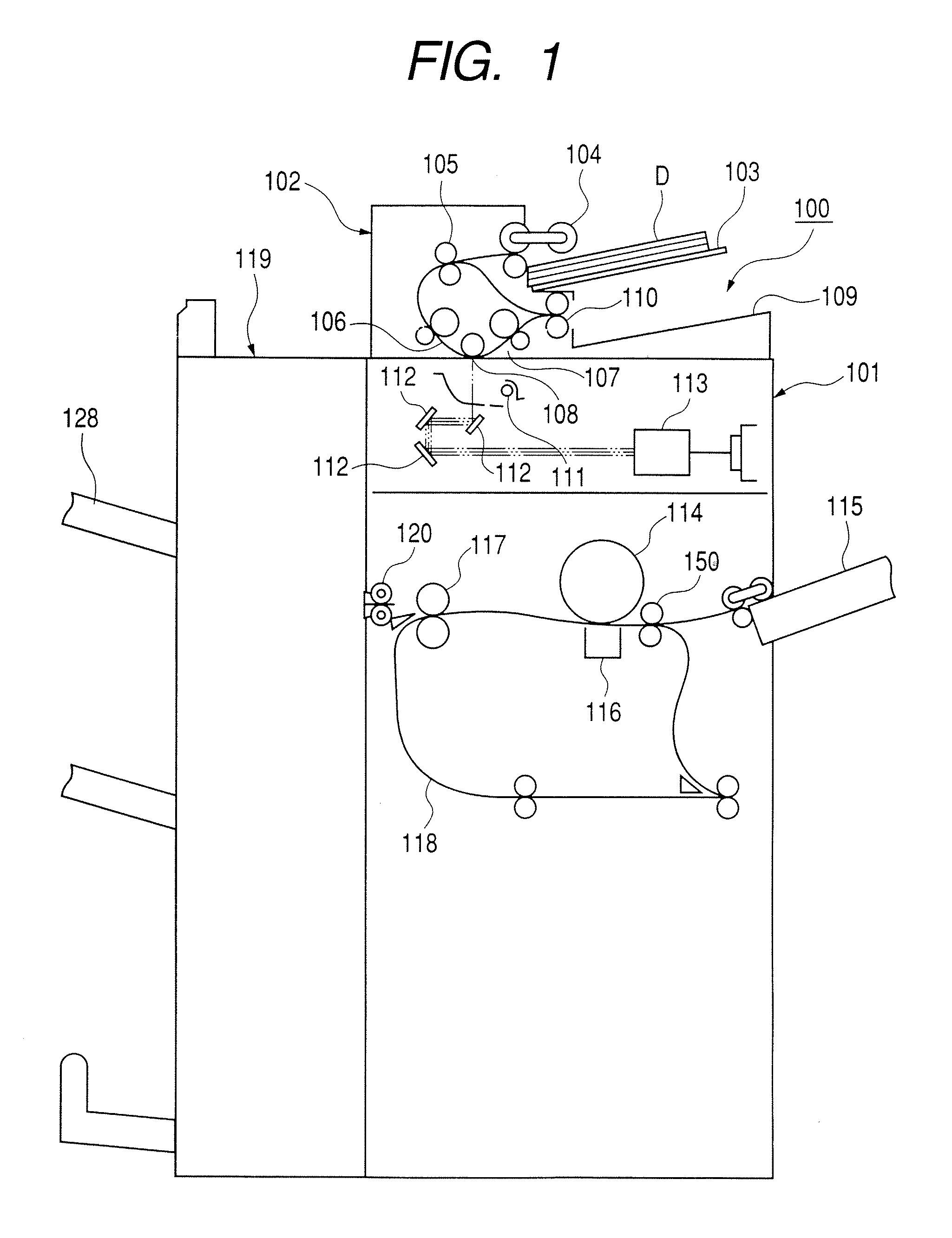
[0091] A sheet processing apparatus of an embodiment of the present invention and a copying machine, which is an example of an image forming apparatus including this sheet processing apparatus, will be hereinafter described with reference to the accompanying drawings. Note that examples of the image forming apparatus include a copying machine, a facsimile apparatus, a printer, and a multifunction machine of these apparatuses, and the image forming apparatus including the sheet processing apparatus is not limited to a copying machine.

[0092] Further, dimensions, numerical values, materials, shapes, a relative arrangement of the components described in this embodiment, and the like are not meant to limit a scope of the present invention only to them unless specifically described otherwise.

[0093] In the description of the embodiments, a case in which the sheet processing apparatus is an optional apparatus, which is constituted to be detachably mountable to an apparatus main body of th...


PUM

PropertyMeasurementUnit
speedaaaaaaaaaa
speedaaaaaaaaaa
speedaaaaaaaaaa

Abstract

A sheet processing apparatus includes: a buffer unit which stores plural supplied sheets with upstream edges in a conveying direction thereof aligned; a processing tray on which sheets discharged from the buffer unit are stacked; and an oscillation roller pair and a return roller which convey the sheet stacked on the processing tray to bring the sheet into abutment against a stopper for receiving the upstream edge of the sheet. The buffer unit is adapted to align the upstream edges of only sheets to be stored before a sheet to be supplied last among the sheets to be stored.

Description

BACKGROUND OF THE INVENTION [0001] 1. Field of the Invention [0002] The present invention relates to a sheet processing apparatus, which is provided, for example, in an apparatus main body of an image forming apparatus such as a copying machine or a printer, and applies processing to sheets to be sent from the apparatus main body. In particular, the present invention relates to a sheet processing apparatus, which can store sheets to be sent while processing is applied to the sheets, and an image forming apparatus including the sheet processing apparatus. [0003] 2. Related Background Art [0004] In recent years, a sheet processing apparatus such as a sorter for sorting sheets, on which an image has been formed, as an option for an image forming apparatus such as an electrophotographic copying machine or a laser beam printer. This kind of sheet processing apparatus is adapted to apply one of sort processing, stitch processing, alignment processing, and the like to sheets. [0005] For ex...

Claims


Application Information

Patent Timeline
Patent Type & Authority Applications(United States)
IPC IPC(8): B65H33/04B65H31/00B42C1/12B65H29/00B65H29/34B65H31/26B65H31/36B65H37/04G03G15/00G03G15/20G06F7/00
CPCB42C1/12B65H31/24B65H31/3027B65H39/10B65H2301/4213B65H2301/4222B65H2301/42262B65H2405/332B65H2511/514B65H2701/1313B65H2801/27G03G15/6538G03G2215/00375B65H2220/01
Inventor HAYASHI, KENICHINAKAMURA, TOMOKAZUWATANABE, NAOTOOBUCHI, YUSUKEKATO, HITOSHINISHIMURA, SHUNSUKETERADA, TETSUYAIWASA, YASUTAKAMATSUKURA, DAISUKEMOTOI, NORIOKUBO, MASAYOSHI
Owner COPYER
Learn More