
Model of sensitivity of a simulated layout to a change in original layout, and use of model in proximity correction

a layout and proximity correction technology, applied in the field of layout design, can solve the problems of cumbersome calculation of the effect of perturbation on each serif, prohibitively expensive second application of process model at each serif, and inability to use fft approach in any commercially available software for full chip, etc., to achieve the effect of reducing memory requirements and facilitating computation

Active Publication Date: 2007-05-03
SYNOPSYS INC
View PDF8 Cites 41 Cited by
  • Summary
  • Abstract
  • Description
  • Claims
  • Application Information

AI Technical Summary

Benefits of technology

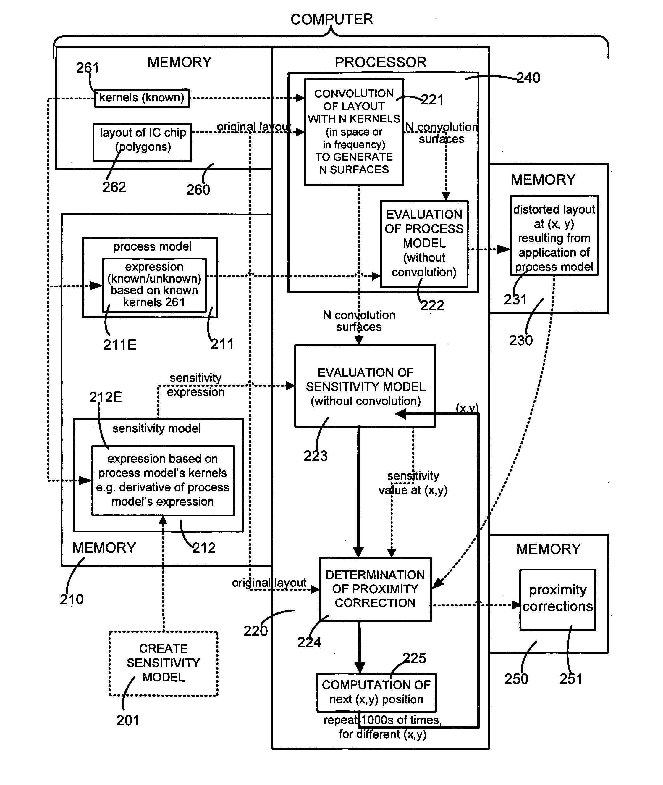
[0068] The prior art second application of the process model at each serif is eliminated in many embodiments of the invention, by use of the sensitivity model. In several embodiments, identifying the effect of each serif on the distorted layout requires an evaluation of the sensitivity model. Such embodiments are superior over the prior art's double application of the process model for three reasons. First, the sensitivity model is based on the process model's kernels and corresponding unperturbed convolution results. There is no need to re-calculate the effect of the perturbation on each of the individual convolution surfaces used in the process model. Second, in the typical case where the process model is 2nd order (non-linear), the sensitivity model is 1st order (linear). This linear model is easier to compute as compared to the non-linear model. Third, since it is not necessary to re-calculate perturbed convolution results, it is not a requirement that one save, modify, or regenerate the intermediate convolution results for each serif (at each (x,y) location), thereby reducing memory requirements.

Problems solved by technology

Note that a second application of the process model is required for every serif, because current prior art known to this inventor does not teach how to separately account for the individual intensity contribution from an individual serif.
When using the method of FFT to calculate convolutions in a process model, the second application of the process model at each serif is prohibitively expensive.
Because there may be between 4 to 40 separate FFT's used in the application of the process model, calculating the effect of the perturbation on each is cumbersome.
Also, to the knowledge of this inventor, an FFT approach is currently not used in any commercially available software for full chip, optical proximity correction, in part because of the inability to calculate the effect of a perturbation quickly.
Hence, Granik's method appears to be too slow for practical applications.
Furthermore, caching intermediate FFT results requires memory.
Assuming between 4-40 FFT's in a typical application, this results in 100 M to 1.2 G Bytes of cached information in Granik's method, a size far too large to be accessed quickly using cache technologies available in today's computers.
Since the process model in practical applications is non-linear, the second call to the process model at each serif is computationally expensive.
In the method discussed next, it is not necessary to save (or regenerate) the intermediate electric fields, and hence, not possible to calculate the process model a second time.
First, the sensitivity model is based on the process model's kernels and corresponding unperturbed convolution results.

Method used


Image

  • Model of sensitivity of a simulated layout to a change in original layout, and use of model in proximity correction
  • Model of sensitivity of a simulated layout to a change in original layout, and use of model in proximity correction
  • Model of sensitivity of a simulated layout to a change in original layout, and use of model in proximity correction

Examples


Embodiment Construction

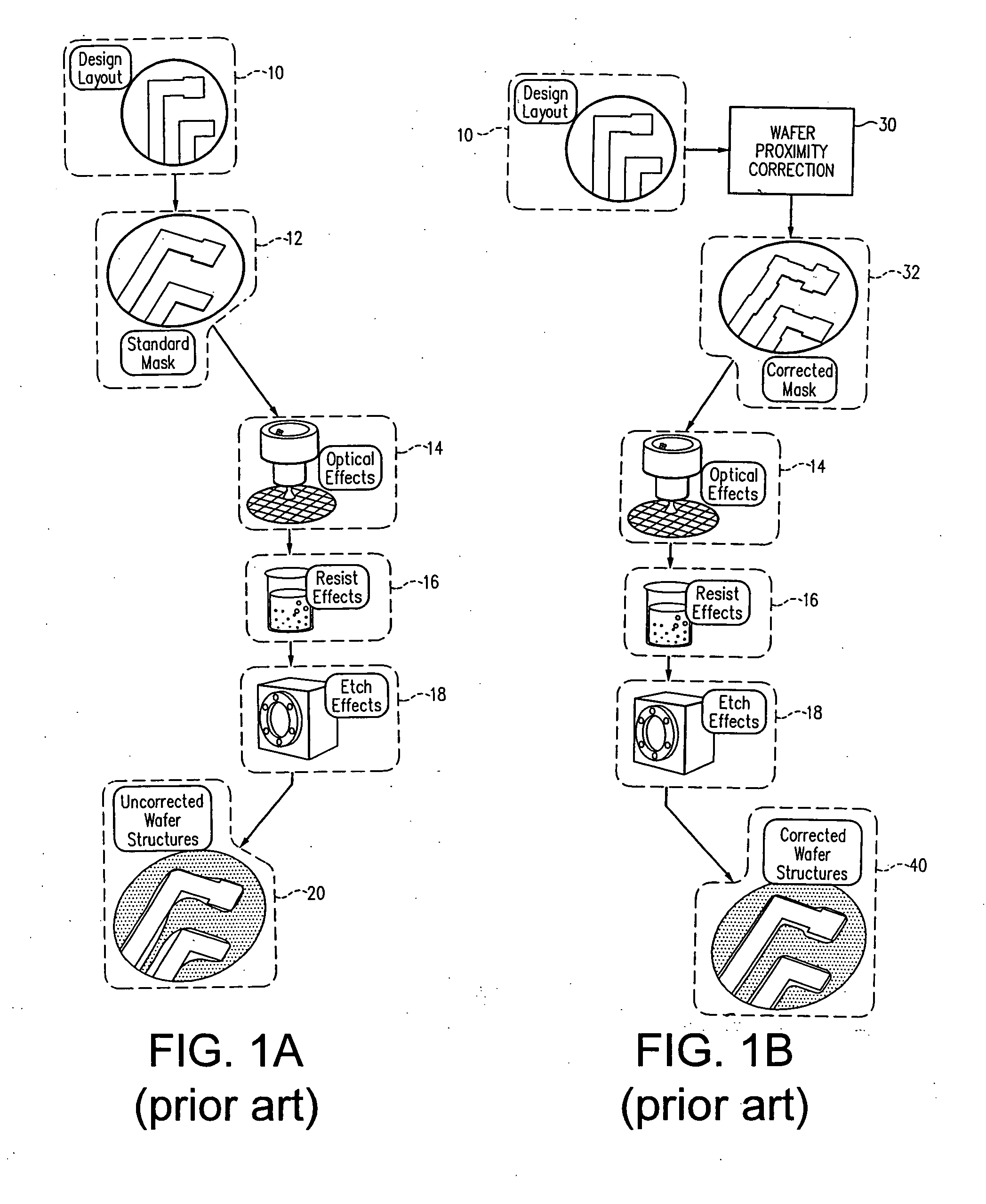
[0090] A memory 210 (FIG. 2) of a computer is encoded, in accordance with the invention, with a model 212 of sensitivity of a layout generated by simulation of fabrication of a wafer (hereinafter “distorted layout”), with respect to a change in an original layout of an integrated circuit (IC) chip that is input to the simulation. The change in original layout may be in any form, such as a serif of unit area or a movement of a polygon edge in the layout by a unit distance. During simulation, the computer evaluates another model, namely a model 211 of a wafer fabrication process (hereinafter “process model”) to generate the distorted layout. A sensitivity model 212 can be created from the process model 211 in any manner, either manually or automatically, and creation of model 212 (as per operation 201 in FIG. 2) in certain illustrative embodiments is described below.

[0091] Distorted layout 231 generated by use of process model 211 includes optical effects 14, resist effects 16, and e...


PUM


Abstract

A memory is encoded with a model of sensitivity of a distorted layout generated by simulation of a wafer fabrication process, with respect to a change in an original layout that is input to the simulation. The sensitivity model comprises an expression of convolution of the original layout with spatial functions (“kernels”) that are identical to kernels of a process model used in the simulation. A difference between the distorted layout and the original layout is computed, and the difference is divided by a sensitivity value which is obtained directly by evaluating the kemel-based sensitivity model, and the result is used to identify a proximity correction (such as serif size or contour movement) to be made to the original layout. Use of a sensitivity model based on a process model's kernels eliminates a second application of the process model to evaluate sensitivity, thereby to reduce memory and computation requirements.

Description

BACKGROUND [0001] 1. Field of the Invention [0002] The invention relates to design of layouts used in lithography of semiconductor wafers. More specifically, the invention relates to a method and an apparatus for applying proximity corrections to layouts of integrated circuit (IC) chips. [0003] 2. Related Art [0004] In the manufacture of integrated circuit (IC) chips, minimum feature sizes have been shrinking according to Moore's law. Currently the minimum feature size is smaller than the wavelength of light used in the optical imaging system. In order to achieve reasonable fidelity (including resolution and depth of focus) between (a) a layout designed in a computer and (b) shapes of circuit elements formed in a wafer after fabrication, a number of reticle enhancement technologies (RET) have been developed over the last decade, such as optical proximity correction (OPC), phase shifting masks (PSM), and sub-resolution assist features. [0005] Proximity correction as performed in prio...

Claims


Application Information

Patent Timeline
IPC IPC(8): G06F17/50G03F1/00G21K5/00G06F19/00
CPCG03F1/144G03F1/36G03F7/70441G03F7/705G06F17/5068G06F30/39
Inventor STIRNIMAN, JOHN P.CRANFORD, MICHEAL D.
Owner SYNOPSYS INC
Learn More