
Driving of plasma display device

Inactive Publication Date: 2007-05-03
SAMSUNG SDI CO LTD
View PDF6 Cites 0 Cited by
  • Summary
  • Abstract
  • Description
  • Claims
  • Application Information

AI Technical Summary

Benefits of technology

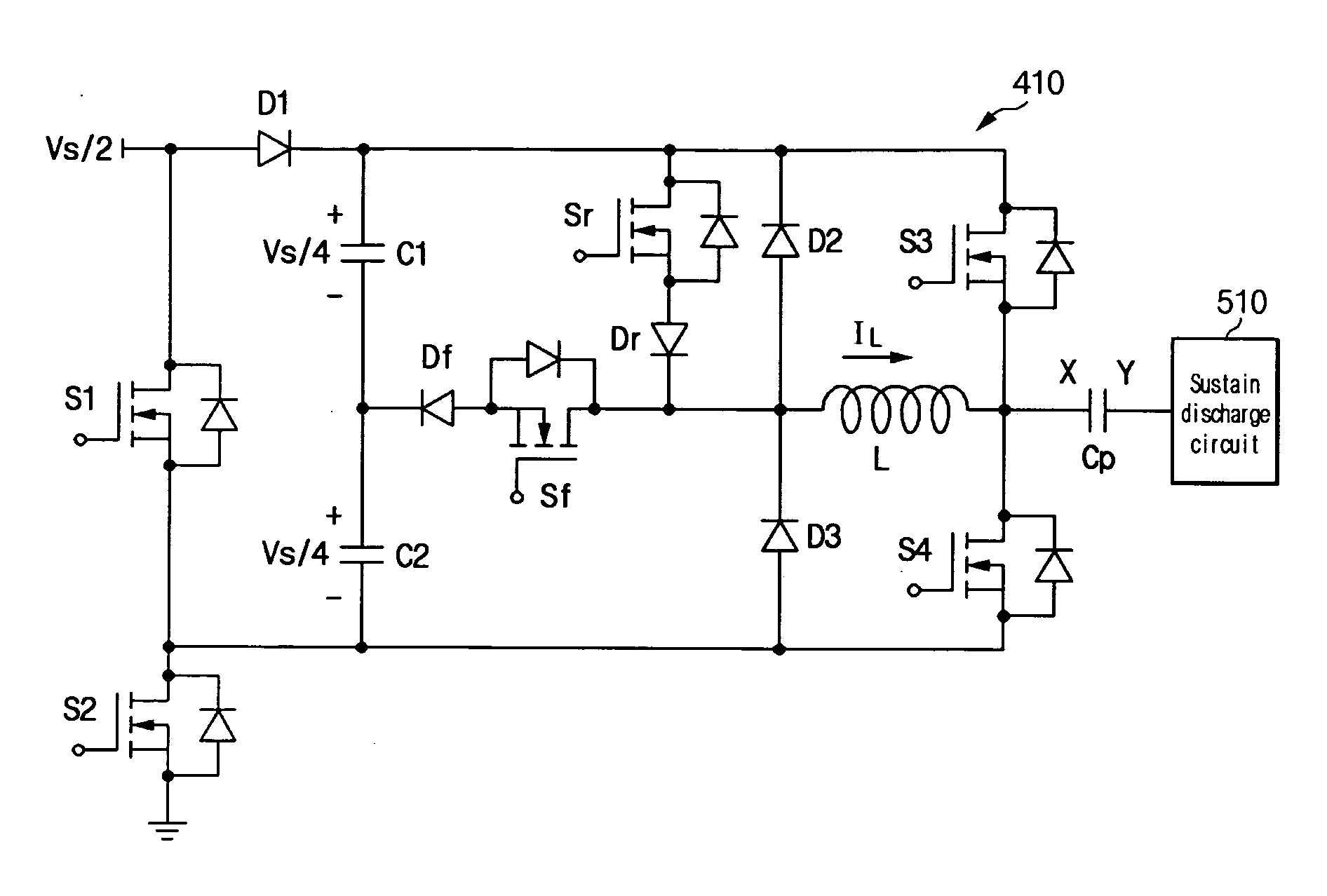
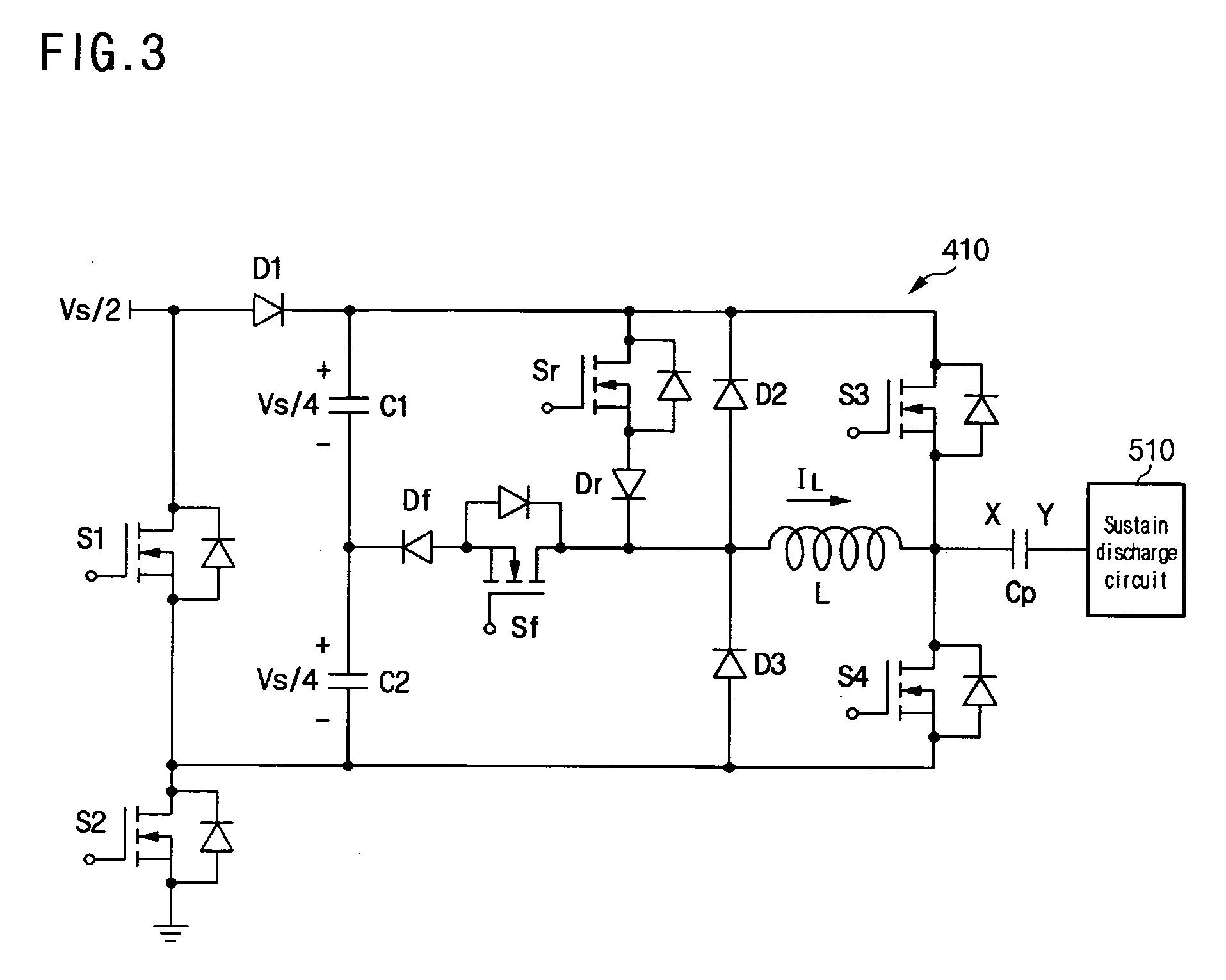
[0017] An exemplary driving method according to another embodiment of the present invention drives a plasma display device having a first electrode and a second electrode. In the driving method, a voltage of the first electrode is increased by applying energy stored in a first capacitor that charges a first voltage and a second capacitor that charges a second voltage to the first electrode through an inductor which is electrically coupled to the first electrode. A third voltage that corresponds to a sum of the first and second voltages is applied to the first electrode through the first and second capacitors.
[0018] The voltage of the first electrode is increased by applying energy stored in a first power source, the first capacitor, and the second capacitor to the first electrode through the inductor, the first power source supplying a fourth voltage. A fifth voltage that corresponds to a sum of the third and fourth voltages is applied to the first electrode through the first power source, the first capacitor, and the second capacitor. The voltage of the first electrode is decreased by recovering the energy stored in the first electrode to the first capacitor and the first power source through the inductor. A sixth voltage that is lower than the fourth voltage is applied to the first electrode. An exemplary driving apparatus according to another embodiment of the present invention drives a plasma display device including a first electrode and a second electrode.
[0019] The driving apparatus includes an inductor, a first capacitor, a second capacitor, a first transistor, a second transistor, a third transistor, a fourth transistor, and a switch. The inductor has a first end electrically coupled to the first electrode. The first capacitor charges a first voltage. The second capacitor charges a second voltage, and has a first end electrically coupled to a first end of the first capacitor. The first transistor is electrically coupled between a second end of the first capacitor and the first electrode. The second transistor is

Problems solved by technology

However, the transistor having such a high withstand voltage may be expensive and increase the production costs of the plasma display devices.

Method used


Image

  • Driving of plasma display device
  • Driving of plasma display device
  • Driving of plasma display device

Examples


Embodiment Construction

[0028] In the following detailed description, only certain exemplary embodiments of the present invention are described. As those skilled in the art would realize, the described embodiments may be modified in various different ways, all without departing from the spirit or scope of the present invention. For the sake of convenience, descriptions of functionally similar parts or elements are not repeated in different embodiments, and like numerals are used to refer to like parts and elements.

[0029] Throughout this specification and the claims, unless explicitly stated to the contrary, the words “comprise” and “include” will be understood to mean inclusion of stated elements and not exclusion of any other elements. In addition, throughout this specification and the claims which follow, the expression of maintaining a voltage at a given level implies that a slight and non-significant variation of a potential difference between two specific points may be acceptable within an allowable ...


PUM


Abstract

A circuit for supplying voltages to an electrode of a plasma display device is disclosed. The circuit includes an inductor connected to the electrode, a first capacitor and a second capacitor serially connected to the first capacitor. The circuit selectively forms certain paths to provide pulses to the electrode to sustain plasma discharges. The circuit provides pulses by increasing the potential of the electrode from a first voltage to a second voltage, maintaining the potential at about the second voltage during a first period, increasing the potential from about the second voltage to a third voltage, maintaining the potential at about the third voltage during a second period, decreasing the potential from about the third voltage to about the first voltage, and maintaining the potential at about the first voltage during a third period. Increasing the potential from the first to second voltages involves supplying energy stored in the first and second capacitors to the electrode via the inductor. Increasing the potential from the second to third voltages involves supplying energy stored in the first and second capacitors to the first electrodes via the inductor and further involves supplying energy from a power source to the electrode via the inductor.

Description

CROSS-REFERENCE TO RELATED APPLICATION [0001] This application claims priority to and the benefit of Korean Patent Application No. 10-2005-0104204 filed in the Korean Intellectual Property Office on Nov. 2, 2005, the entire content of which is incorporated herein by reference. BACKGROUND OF THE INVENTION [0002] 1. Field of the Invention [0003] The present invention relates to a plasma display device. More particularly, the present invention relates to driving of a plasma display device. [0004] 2. Description of the Related Art [0005] A plasma display device is a flat panel display that uses plasma generated by a gas discharge process to display characters or images. To implement variations in brightness of image display, the time for displaying a single frame is divided into a plurality of time segment called “subfields”. In each subfield, cells to be turned on for emitting light are selected by a short plasma discharge called “address discharge”. Still in each subfield, these selec...

Claims


Application Information

Patent Timeline
IPC IPC(8): G09G3/28G09G3/288G09G3/294G09G3/296
CPCG09G3/294G09G3/2965G09G2310/066G09G3/296
Inventor KWAK, SANG-SHINYANG, HAK-CHEOLKIM, JOON-YEONJEONG, YONG-JIN
Owner SAMSUNG SDI CO LTD
Learn More