Method for driving active display
- Summary
- Abstract
- Description
- Claims
- Application Information
AI Technical Summary
Benefits of technology
Problems solved by technology
Method used
Image


Examples
Embodiment Construction
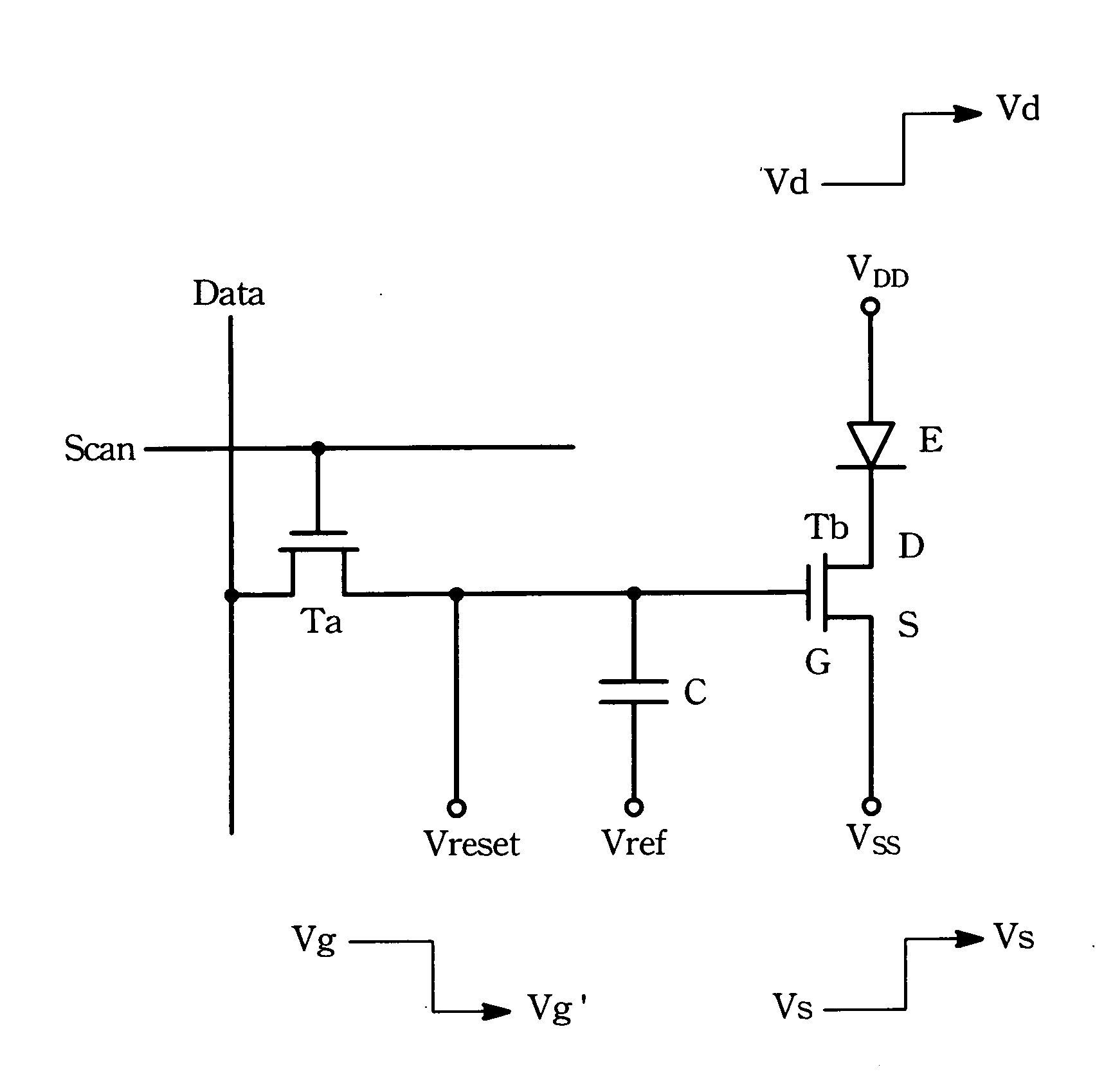
[0024]FIG. 2 shows an electric circuit diagram of a pixel of an active electro luminescent display (ELD). The pixel has a scan line Scan, a data line Data, a switching transistor Ta, a driving transistor Tb, an luminescent element E, and a capacitor C. The source electrode and the gate electrode of the switching transistor Ta are electrically connected to the data line Data and the scan line Scan, respectively. The drain electrode D and source electrode S of the driving transistor Tb are electrically connected to the luminescent element E and a secondary voltage source, respectively. The gate electrode G of the driving transistor Tb is electrically connected to the drain electrode of the switching transistor Ta, the capacitor C, and a resetting voltage source Vreset. The luminescent element E has an electrode electrically connected to the drain electrode D of the driving transistor Tb and another electrode electrically connected to a displaying voltage source.
[0025] The method with...
PUM
 Abstract
Description
Claims
Application Information
 - R&D
- Intellectual Property
- Life Sciences
- Materials
- Tech Scout
- Unparalleled Data Quality
- Higher Quality Content
- 60% Fewer Hallucinations
Browse by: Latest US Patents, China's latest patents, Technical Efficacy Thesaurus, Application Domain, Technology Topic, Popular Technical Reports.
© 2025 PatSnap. All rights reserved.Legal|Privacy policy|Modern Slavery Act Transparency Statement|Sitemap|About US| Contact US: help@patsnap.com