
Amphibious vehicle

a technology for amphibious vehicles and vehicles, applied in the field of amphibious vehicles, can solve the problems of restricting the power and/or road speed of certain types of vehicles, and imposing undesired high speed and acceleration potential on the vehicl

Active Publication Date: 2007-04-26
GIBBS TECH
View PDF6 Cites 17 Cited by
  • Summary
  • Abstract
  • Description
  • Claims
  • Application Information

AI Technical Summary

Benefits of technology

"The present invention provides an amphibious vehicle that can operate on land and water. The vehicle has three wheels, handlebars for steering, a seat, and a power plant for driving one of the wheels. The power control means controls the amount of power sent to the driven wheels, with more power sent to the jet drive or propeller in water mode. The speed control means offers resistance to motion on land without limiting the vehicle's speed over water. The power plant outputs power via a rotating output shaft, and the speed control means limits the rotational speed of the driven wheels when the vehicle is on land. These features make the amphibious vehicle more versatile and efficient for both land and water use."

Problems solved by technology

Such power levels may however be capable of imparting undesirably high speed and acceleration potential to the vehicle when used on land.
Moreover, legislative requirements in certain parts of the world actually restrict power and / or road speed for certain types of vehicles.

Method used


Image

  • Amphibious vehicle
  • Amphibious vehicle
  • Amphibious vehicle

Examples


Embodiment Construction

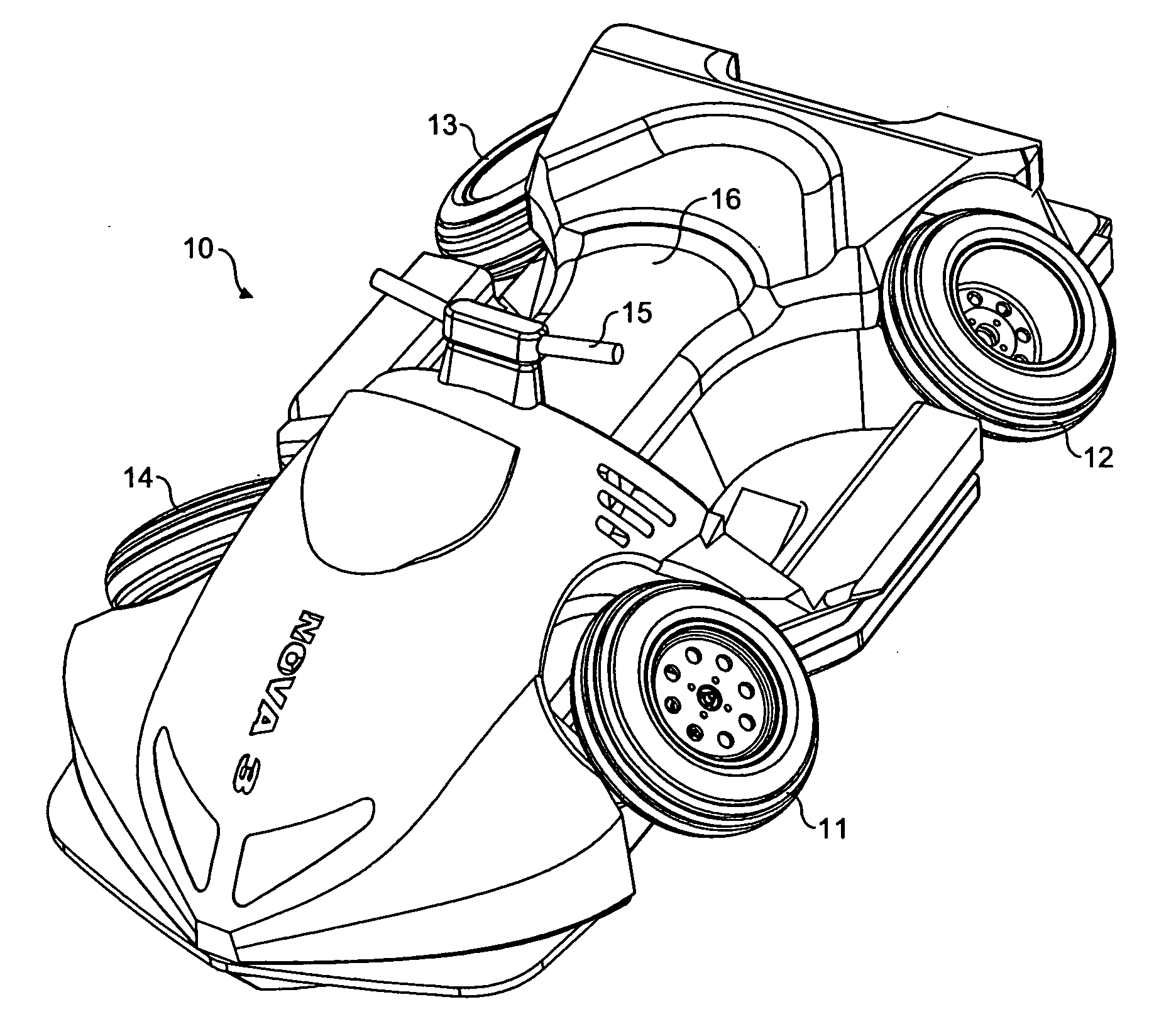
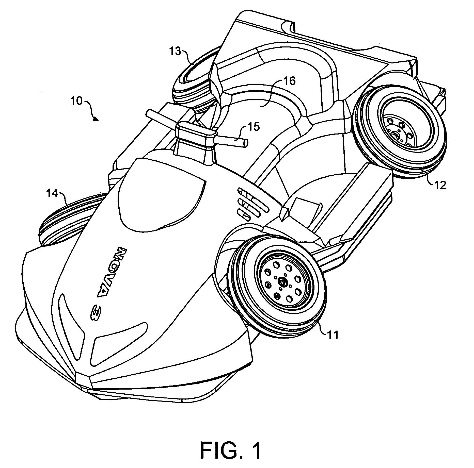
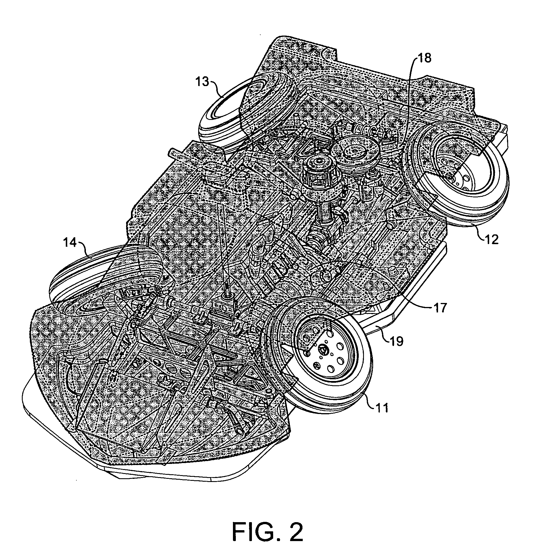
[0010] Turning firstly to FIG. 1 there can be seen in the Figure an amphibious vehicle 10 having four wheels 11, 12, 13 and 14, handlebars 15 for steering the front wheels 11 and 14 and a sit-astride seat 16. As can be seen in FIG. 2, there is located inside the vehicle a gasoline reciprocating piston multi-cylinder internal combustion engine 17 which when the vehicle is in land mode drives the two rear wheels 13 and 12 to rotate. The vehicle also has a jet drive 18 at the rear of the vehicle which is driven by the engine 17 to propel the vehicle 10 when operating in water mode.

[0011] The hull 19 of the vehicle has on its lower surface a planing surface (not shown) to enable the vehicle to plane across the water when in its water mode. To facilitate this the road wheels 11, 12, 13 and 14 are connected to the remainder of the vehicle by a suspension system which allows them to be moved between an extended position (as shown in FIG. 3) for land use and a retracted position (as shown ...


PUM


Abstract

Amphibious vehicle needs less power on land than on water. A control system is provided to limit power and / or speed on land, using: restriction of flow of fuel, air, or exhaust gases; heated intake air; exhaust gas recirculation; declutching of a supercharger; bypassing of a turbocharger; a variable throttle stop, dual throttles, or a switchable throttle damper; cylinder or intake valve deactivation; a dual length intake manifold; dual mode ignition or engine mapping; dual fuel—gasoline on water, compressed natural gas on road; variable compression ratios or valve timing; a clutch designed to slip; automatic brake application; or aerodynamic brakes. The suspension may tilt the vehicle to increase aerodynamic resistance. The road transmission may be geared to limit maximum speed. High rolling resistance tyres or twin engines may be used. A sensor on retractable suspension may indicate whether the vehicle is on land or on water.

Description

BACKGROUND OF THE INVENTION [0001] The present invention relates to an amphibious vehicle. [0002] The amphibious vehicle contemplated by the present invention is lightweight in nature. Nevertheless, it requires a power plant with a certain amount of power output in order that the vehicle on water can get up on to the plane and travel as a planing vehicle. Such power levels may however be capable of imparting undesirably high speed and acceleration potential to the vehicle when used on land. Moreover, legislative requirements in certain parts of the world actually restrict power and / or road speed for certain types of vehicles. For example, a Low Speed Vehicle in the USA must not be capable of exceeding 25 mph on the road while in Europe a road legal All Terrain Vehicle must be restricted to an engine power output of less than 15 kW / 20 brake horsepower. SUMMARY OF THE INVENTION [0003] In a first aspect the present invention provides an amphibious vehicle comprising at least three whee...

Claims


Application Information

Patent Timeline
Patent Type & Authority Applications(United States)
IPC IPC(8): B60F3/00
CPCB60F3/0007B60F3/0069B60F2301/04B60F3/00
Inventor GIBBS, ALAN TIMOTHYJENKINS, NEIL GRAHAM
Owner GIBBS TECH
Learn More