
Debit or credit cardholder

a credit card and cardholder technology, applied in the field of plastic card holders, can solve the problems of unauthorized observer storing or remembering data for subsequent illicit use, affecting the use of the data, and at times superfluous carrying a wallet or purs

Inactive Publication Date: 2007-04-26
HIGHER ONE
View PDF12 Cites 9 Cited by
  • Summary
  • Abstract
  • Description
  • Claims
  • Application Information

AI Technical Summary

Benefits of technology

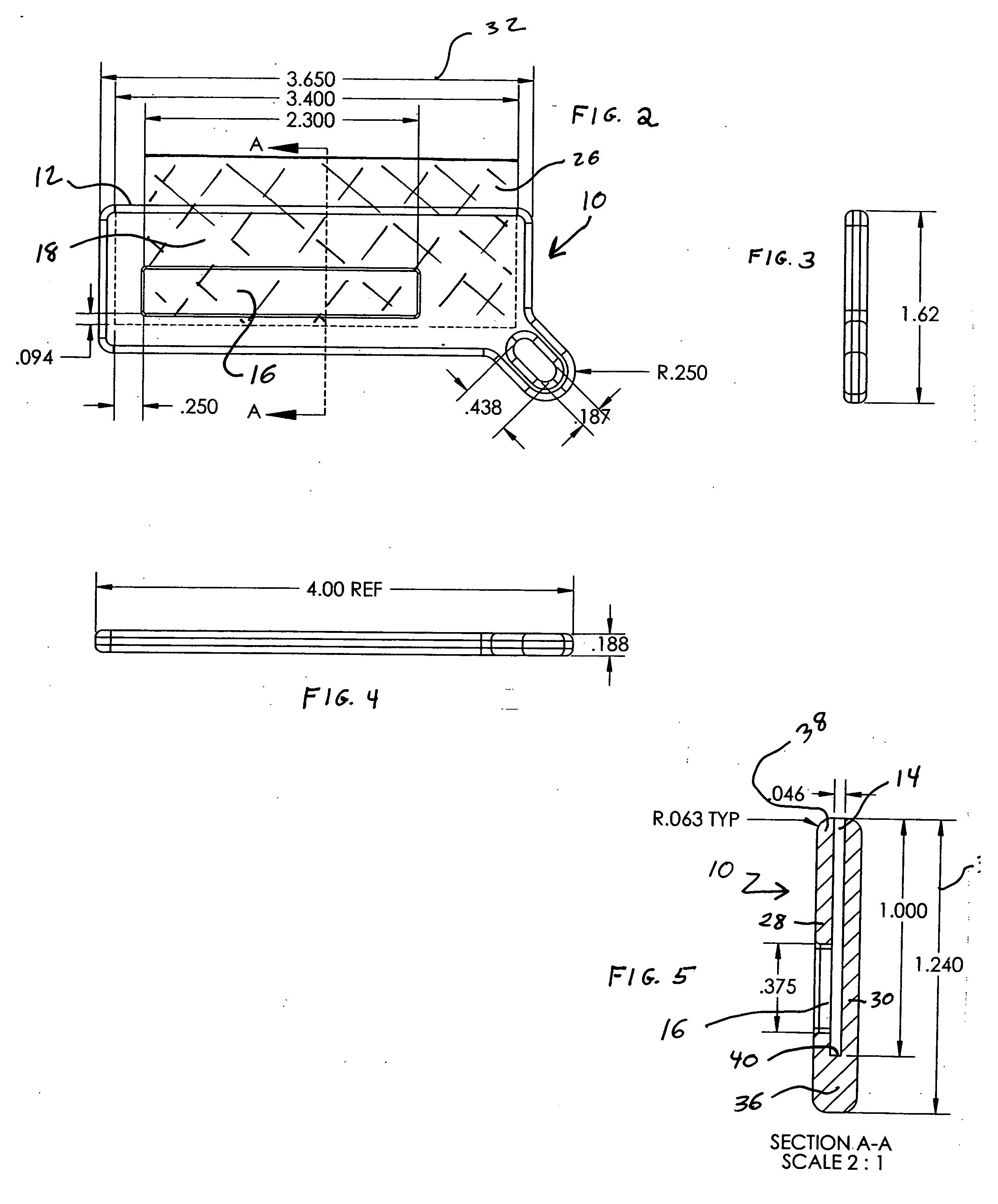
[0011] In accordance with the invention, there is provided a protective case for a plastic data card. This protective case includes a non-transparent housing having a first planar surface and a second planar surface both having a desired length and a desired height. The first planar surface and the second planar surface are joined together at a first end with a slit separating the first planar surface from the second planar surface. This slit extends inward from an opposing second end of said transparent housing. The slit terminates proximate the first end at a distance from the first end which is effective to position desired data on the plastic data card at an effective distance from the first end. A transparent window is formed in the first planar side and is effective to expose the desired data. The height of the second planar surface is effective to expose a magnetic stripe on the plastic data card.

Problems solved by technology

However, with the wide-spread acceptance of these cards, carrying a wallet or purse is at times superfluous.
Features of the plastic data cards make the prior art protective cases less desirable.
Removal of the card for use introduces a risk that an unauthorized observer will surreptitiously record or remember the data for subsequent illicit use.

Method used


Image

  • Debit or credit cardholder
  • Debit or credit cardholder
  • Debit or credit cardholder

Examples


Embodiment Construction

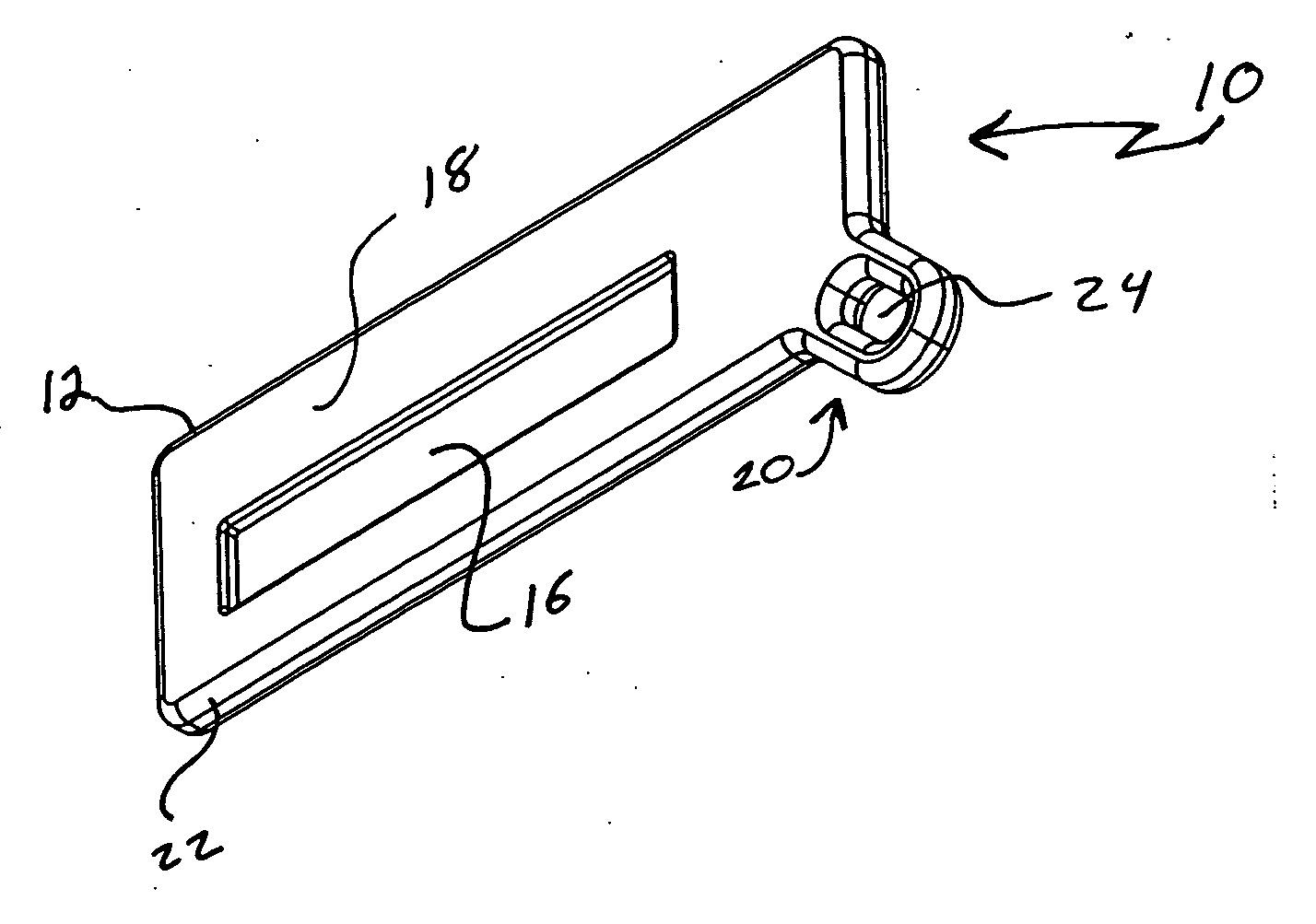
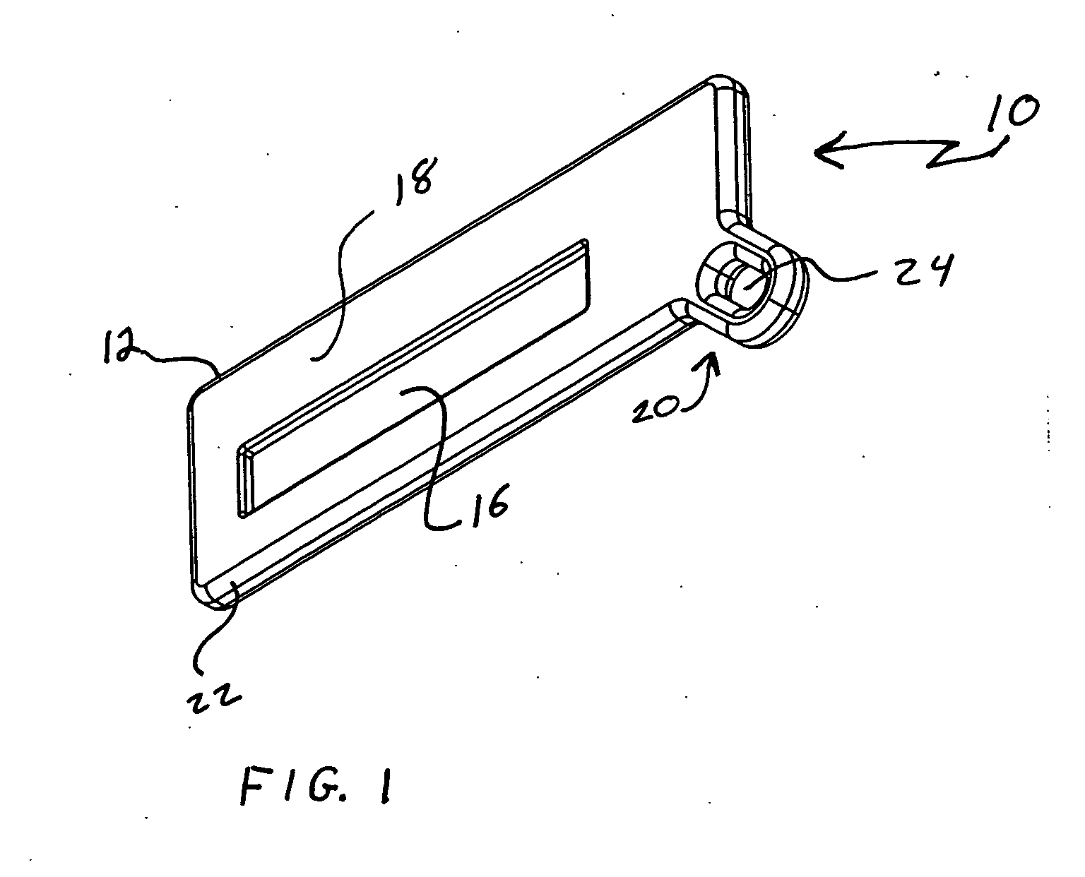
[0018]FIG. 1 shows in perspective view a plastic cardholder or protective case 10 of the invention. The protective case 10 is especially suited for housing plastic data cards, such as debit / credit / ID cards, having a data encoded magnetic data strip located on a top half of the back of the card. The plastic cardholder 10 is preferably made from a non-transparent rigid plastic, having limited flexibility. An exemplary plastic is injection molded polycarbonate. Other plastic, metals and composites may also be used to form the protective case. Processes other than injection molding may also be used.

[0019] By non-transparent, it is meant that data on the card, either embossed or printed, readable when the card is outside the protective case 10 is not readable when the card is inside the protective case. The embossed or printed data is obscured such as through the use of an opaque plastic, a translucent plastic or a patterned plastic.

[0020] A plastic data card is inserted into a slit fo...


PUM


Abstract

There is provided a protective case for a plastic data card. This protective case includes a non-transparent housing having a first planar surface and a second planar surface both having a desired length and a desired height. The first planar surface and the second planar surface are joined together at a first end with a slit separating the first planar surface from the second planar surface. This slit extends inward from an opposing second end of said transparent housing. The slit terminates proximate the first end at a distance from the first end which is effective to position desired data on the plastic data card at an effective distance from the first end. A transparent window is formed in the first planar side and is effective to expose the desired data. The height of the second planar surface is effective to expose a magnetic stripe on the plastic data card.

Description

CROSS REFERENCE TO RELATED APPLICATION(S) [0001] This application claims the benefit of Provisional Application No. 60 / 728,621, filed on Oct. 20, 2005, entitled “Debit or Credit Cardholder”, which is incorporated by reference in its entirety herein.BACKGROUND OF THE INVENTION [0002] 1. Field of the Invention [0003] This invention relates to a cardholder for plastic cards, such as credit cards or debit cards. More particularly, a non-transparent cardholder permits access to the cardholder's name and information stored on magnetic media while obscuring the card number from view. [0004] 2. Description of the Related Art [0005] The use of credit cards, debit cards, automated teller machine (ATM) cards, identification cards and the like (collectively hereinafter referred to as plastic data cards) is ubiquitous. As these cards are accepted in lieu of cash at ever lower cost denominations, such as vending machines and fast food restaurants, the need to carry cash is reduced. Traditionally,...

Claims


Application Information

Patent Timeline
Patent Type & Authority Applications(United States)
IPC IPC(8): A45C11/18
CPCA45C11/182A45C2200/10
Inventor DECKER, DAVID D.GLASS, SEAN P.LASATER, MILES H.RAKACZKI, ANDREW M.VOLCHEK, MARK T.
Owner HIGHER ONE
Learn More