
Method for predictive maintenance of a machine

a technology for predictive maintenance and machines, applied in the field of method for predictive maintenance of machines, can solve the problems of limiting its usefulness, cbm technology, and limiting the usefulness of a machine, so as to reduce the amount of insignificant information, reduce the need for human intervention, and reduce the dimensionality of the feature space

Inactive Publication Date: 2007-04-19
FORD MOTOR CO
View PDF3 Cites 84 Cited by
  • Summary
  • Abstract
  • Description
  • Claims
  • Application Information

AI Technical Summary

Benefits of technology

[0010] The input to the PdM Agent is a feature vector that characterizes the status of the equipment being monitored. The features may include time, frequency or energy characteristics, process parameters or other measured attributes. Some features which may used by the PdM Agent for machine health monitoring of rotating equipment include time domain features such as time domain data statistics and auto regressive (AR) model parameters. Time domain features can be calculated directly from raw vibration signals picked up by one or more sensors attached to the machine being monitored. Time domain data statistics include such things as root mean square (RMS), crest factor, variance, skewness, and kurtosis. Auto regressive model parameters may use the Burg method to fit a predefined order (p) of an AR model to the input signals by minimizing the forward and backward prediction errors, while constraining the AR parameters to satisfy the Levinson-Durbin recursion.
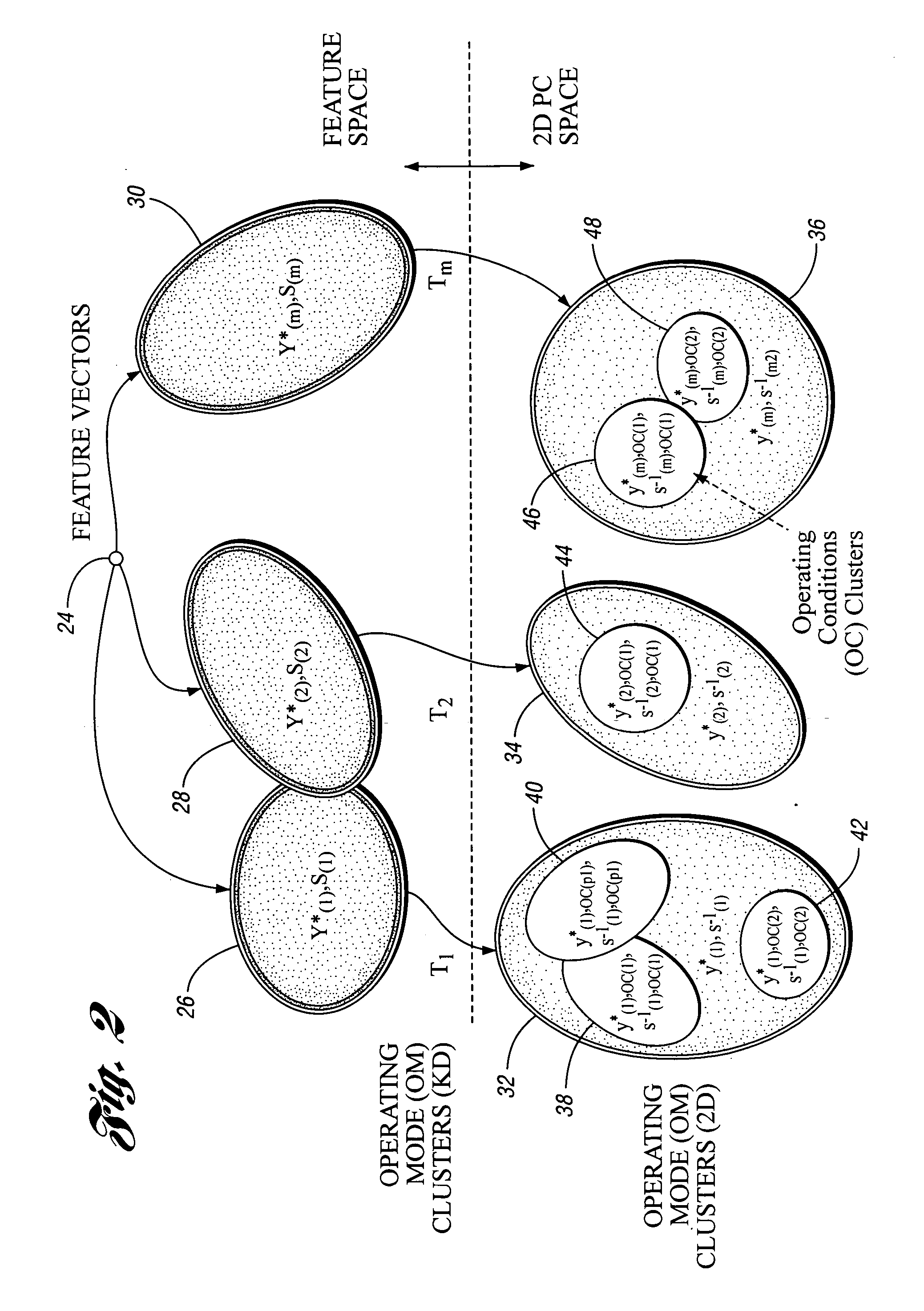
[0015] Another aspect of using the OM clusters, is that their relative stability and repetitive feature patterns allow them to be used to define local mappings between the K-dimensional (K-D) feature space and the two-dimensional space of the first two principal components (PC's). Use of the K-D to 2-D transformation reduces dimensionality of the feature space, decreases the amount of insignificant information, and allows for visualization of the decision making process. The covariance matrices associated with each of the OM clusters are used to update the mappings transforming the features in the OM clusters to their 2-D images in the co-domain space of the first two PC's. Therefore, each of the OM clusters in the feature space has a 2-D counterpart that includes multiple evolving 2-D OC clusters.
[0016] Another embodiment of the present invention provides a diagnostics and prognostics framework (DPF) that is relatively independent of the type of physical equipment under consideration. Much of the modeling and estimation procedures employed by the DPF are based on unsupervised learning methods, which reduce the need for human intervention. The procedures are also designed to temporally evolve parameters with monitoring experience for enhanced diagnostic / prognostic accuracy. The framework also makes a provision for incorporating end-user feedback for enhancing the diagnostic / prognostic accuracy.
[0018] Given that equipment behavior evolves because of such processes as wear-in, maintenance, and wear-out, the DPF is configured to effectively track this non-stationary behavior. The DPF employs a cluster tracking procedure using an optimal exponential waiting scheme. In particular, it employs the following two strategies to enhance the performance of the diagnostics engine. First, the on-line determination of an optimal exponential discounting factor ensures that the cluster tracking is effective in matching the rate of evolution of the equipment operating mode behavior. Second, the DPF includes a provision to allow differing exponential discounting factors for different clusters to further enhance the performance of the diagnostics engine. The discounting factor is optimized based on an objective function that employs a generalized statistical distance (also called Mahalanobis distance) cost function in the dominant PC space.
[0021] The invention also provides a method for predictive maintenance of a machine, which includes collecting feature data for the machine while the machine is operating. The feature data includes a plurality of feature vectors. At least some of the feature vectors are standardized to facilitate compatibility between the standardized feature vectors. At least some of the standardized feature vectors are transformed into corresponding two-dimensional feature vectors. At least some of the two-dimensional feature vectors are clustered, based on operating modes of the machine, thereby forming a plurality of two-dimensional operating mode clusters. Additional feature data is collected while the machine operating. The additional feature data includes a plurality of additional feature vectors. At least some of the additional feature vectors are standardized, and at least some of the additional standardized feature vectors are transformed into corresponding additional two-dimensional feature vectors. An algorithm is applied to at least some of the additional two-dimensional feature vectors to facilitate a comparison between the operation of the machine when the feature data was collected and operation of the machine when the additional feature data was collected. This provides predictive maintenance information for the machine.

Problems solved by technology

Although there are a variety of systems and methods for monitoring and maintaining machinery and equipment, each has one or more inherent limitations which limit its usefulness.
One limitation of this type of system is that during the process of monitoring the machine features, the thresholds remain unchanged unless an expert interferes to force their recalculation.
Another limitation of conventional machine monitoring methods and condition-based maintenance (CBM) technologies is that their application is limited to a particular machine.
While this may lead to accurate information about a particular machine, such technologies are extremely limiting when it comes to widespread deployment for a wide variety of equipment.

Method used


Image

  • Method for predictive maintenance of a machine
  • Method for predictive maintenance of a machine
  • Method for predictive maintenance of a machine

Examples


Embodiment Construction

)

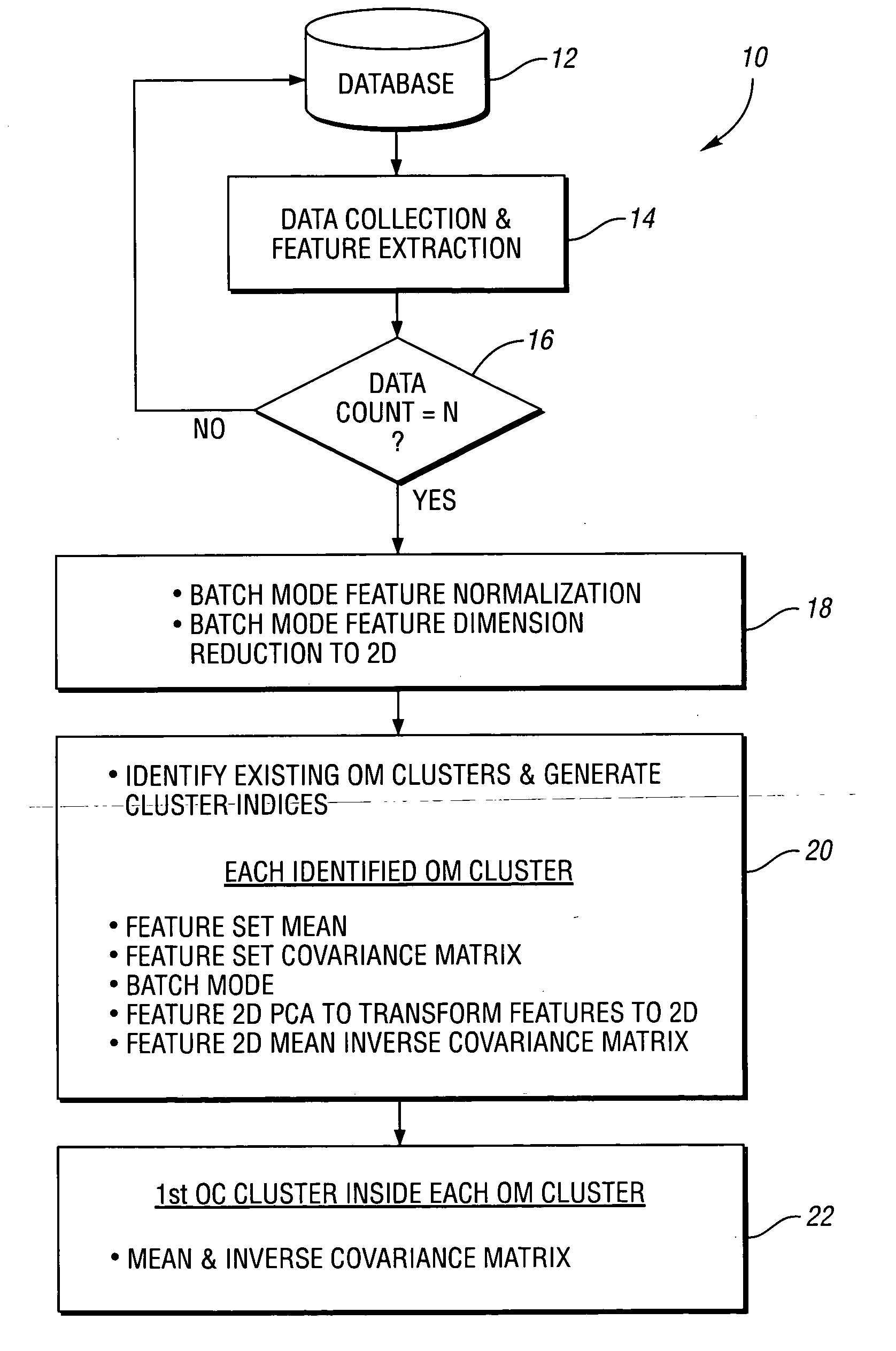
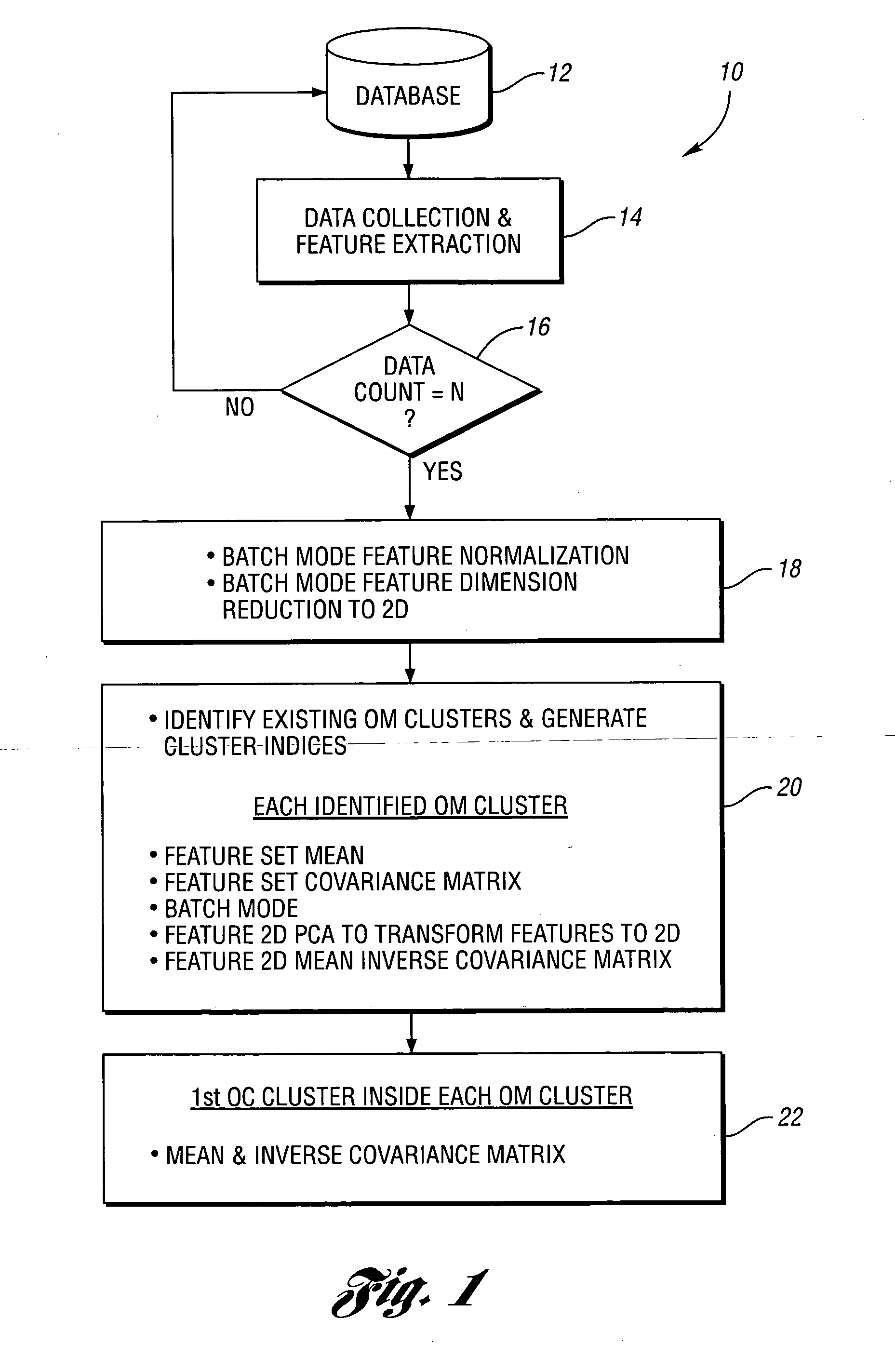
[0030]FIG. 1 shows a flow chart 10 illustrating a portion a method used by a PdM Agent in accordance with the present invention. There are two execution phases in the PdM Agent algorithm—an initialization phase and a monitoring phase. Both phases are based on unsupervised learning. The initialization phase, shown in FIG. 1, is optional; however, its execution can have a positive effect on the performance of the learning algorithms in the monitoring phase. During the initialization phase, initial operating modes are identified and their corresponding parameters are calculated in a batch mode. Once the initialization phase is performed, the PdM Agent enters a monitoring phase which is described below.

[0031] Both the initialization and monitoring phases are preceded by a feature extraction phase wherein a set of features is extracted from the time domain sensor signal. For example, a machine such as a fan, compressor, pump, etc. may have attached to it one or more sensors configured ...


PUM


Abstract

A method for predictive maintenance of a machine includes collecting feature data for the machine which includes a plurality of feature vectors. At least some of the feature vectors are standardized to facilitate compatibility between different vectors. At least some of the standardized feature vectors are transformed into corresponding two-dimensional feature vectors. At least some of the two-dimensional feature vectors are clustered together based on operating modes of the machine. Similar steps are performed on additional feature data collected from the machine. Recently gathered two-dimensional feature vectors are compared to previously clustered feature vectors to provide predictive maintenance information for the machine.

Description

BACKGROUND OF THE INVENTION [0001] 1. Field of the Invention [0002] The present invention relates to a method for predictive maintenance of a machine. [0003] 2. Background Art [0004] Although there are a variety of systems and methods for monitoring and maintaining machinery and equipment, each has one or more inherent limitations which limit its usefulness. For example, many condition-monitoring algorithms operate by continuously comparing newly extracted features—i.e., machine conditions—to their corresponding baseline values. These baseline characteristics are essentially the statistical means of the features collected during the setup phase. The diagnostic capabilities of conventional predictive maintenance systems are based on applying different types of thresholds, templates, and rules, to quantify the relationship between the current feature values and their baseline counterparts. [0005] One limitation of this type of system is that during the process of monitoring the machin...

Claims


Application Information

Patent Timeline
IPC IPC(8): G10L15/06
CPCG05B23/0221G05B23/0283G06K9/6298G06F18/10
Inventor FILEV, DIMITARTSENG, FLINGFARQUHAR, GARYCHESNEY, DAVEHAMIDIEH, YOUSSEFBARUAH, PUNDARIKAKSHACHINNAM, RATNA BABU
Owner FORD MOTOR CO
Learn More