Eureka AIR delivers breakthrough ideas for toughest innovation challenges, trusted by R&D personnel around the world.

Compact high-power acoustic tone generator

a high-power, tone generator technology, applied in the direction of hydraulic/pneumatic audible signalling, mechanical vibration separation, signalling system, etc., can solve the problems of inefficient sound generation, deficiency of conventional edge-tone generators, and large size, so as to interrupt the production of high-power sound and stabilize the output acoustical power and tonal properties

Inactive Publication Date: 2007-04-19
CLECKLER JAY B +1
View PDF6 Cites 6 Cited by
  • Summary
  • Abstract
  • Description
  • Claims
  • Application Information

AI Technical Summary

Benefits of technology

[0006] The combustion or chemical / energetic reaction of one or more solid and / or liquid chemicals used as the source of pressurized gas is similar to a rocket engine or a gas generator which turns liquid and / or solid fuels into relatively massive volumes of pressurized gas. Small amounts of the liquid or solid fuel are used to replace large volume systems such as storage tanks, compressors or steam boilers. As such, the use of solid and / or liquid fuels renders greatly reduced system size compared to the conventional design.
[0008] In the case of edge tone generators, a physical resonant cavity assembly must be included around the effluent flow to provide feedback serving the purpose of stabilizing the output acoustical power and tonal properties. The physical assembly may also prevent dust or foreign objects from entering the field of effluent flow and thus interrupting the production of high-power sound.

Problems solved by technology

The conventional edge-tone generators are deficient in a number of areas.
For example, the output power and the tonal qualities are unstable, the sound generation is inefficient, and the size typically too large.
The conventional form of the source of pressurized gas includes a compressor, a storage tank or a steam boiler, which are all prohibitively large for portable applications.

Method used


Image

  • Compact high-power acoustic tone generator
  • Compact high-power acoustic tone generator
  • Compact high-power acoustic tone generator

Examples


Embodiment Construction

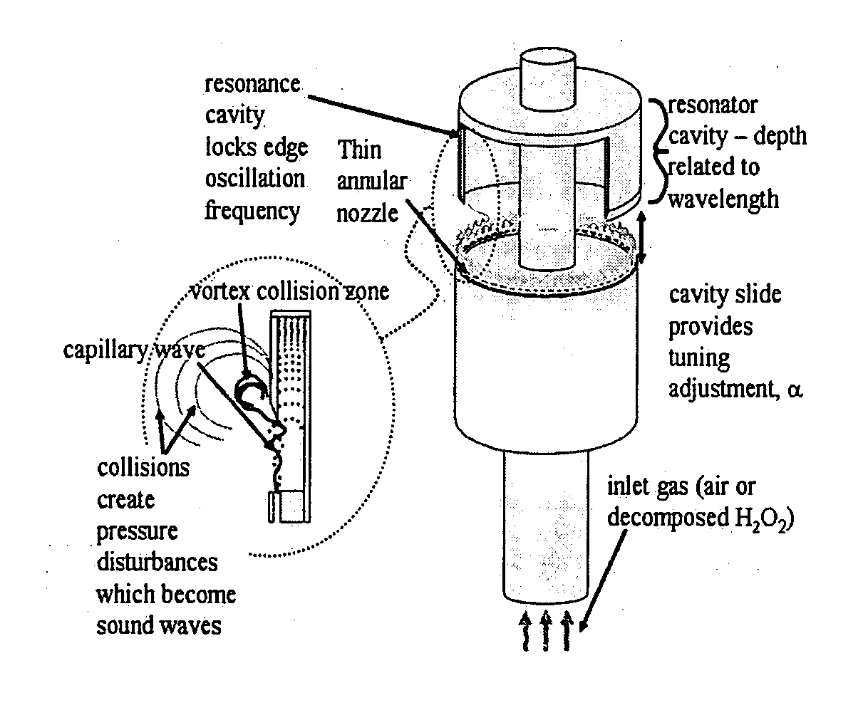
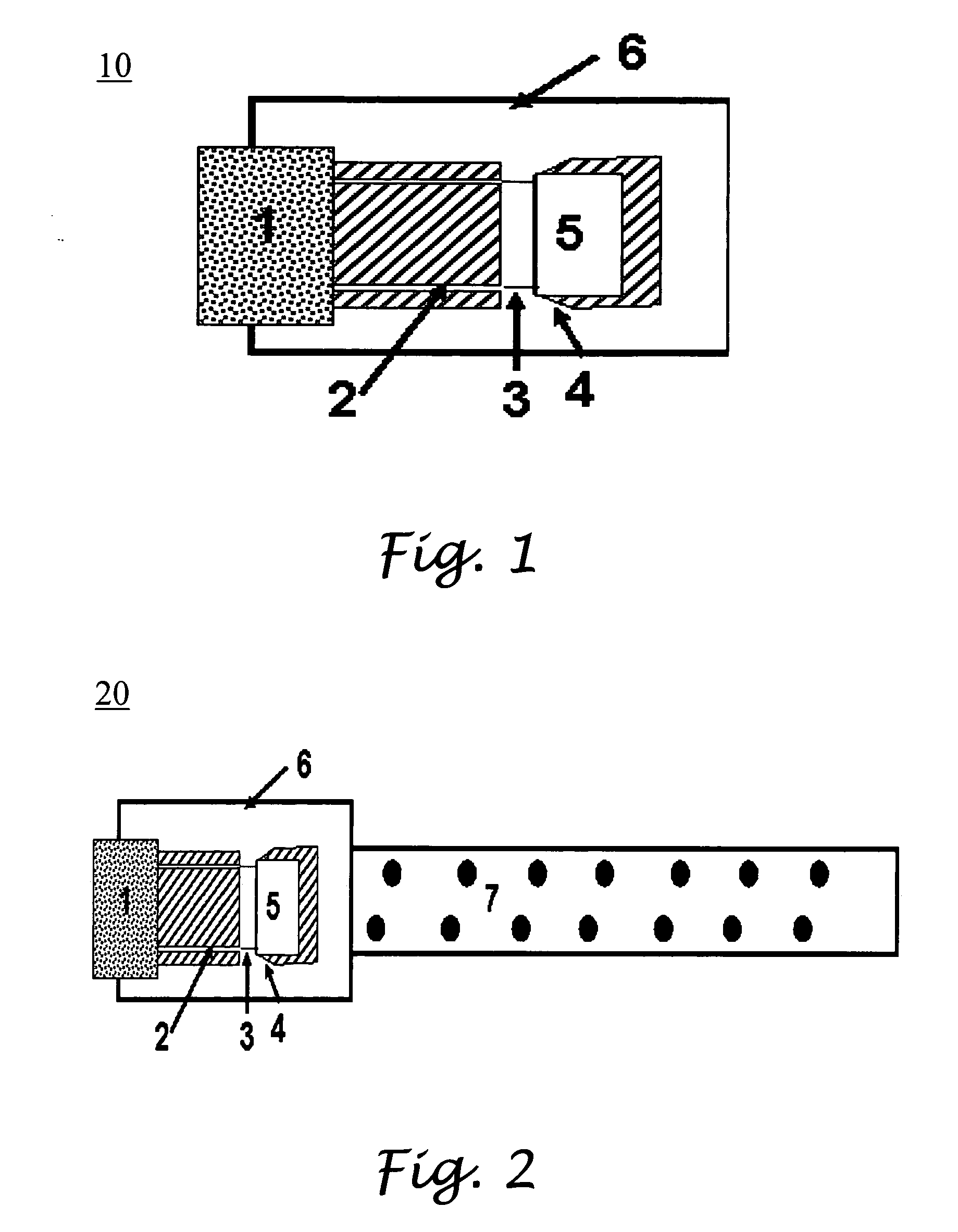
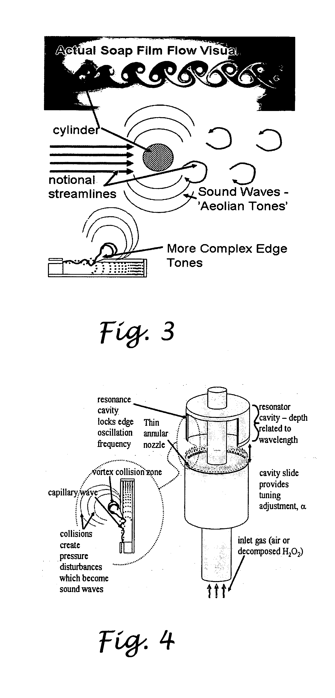
[0018]FIG. 1 illustrates a cross sectional view of an embodiment of a high-power acoustic device 10. As shown, the high-power acoustic device 10 includes a source of pressurized gas 1, in which a concentrated hydrogen peroxide monopropellant is decomposed into pressurized steam and oxygen. The effluent gas, that is, the pressurized gas and oxygen in this embodiment, is then pushed through a thin channel 2 and then ejected as a free jet 3 towards a wedge 4 extending around a bottom rim of a housing which surrounds a resonance cavity 5 therein. The free jet 3 is then caused to flow above or below the wedge 4, which ultimately results in the production of high-power sound. The high-power acoustic device 10 further comprises an outer housing 6 for concentrating the high-power sound therein and partially reflecting the high-power sound towards the wedge 4 to provide feedback. FIG. 2 shows a modification 20 of the high-power acoustic device 10. As shown, the high-power acoustic device 10 ...


PUM


Abstract

An acoustic device operative to generate high-power acoustic tones having a combustion based or chemical reaction based fluidic power source, an aeroacoustic generator, an assembly to provide feedback, and an array hosing that shapes the output pattern of the sound waves. The combustion or chemical / energetic reaction of one or more solid and / or liquid chemicals used as the source of pressurized gas is similar to a rocket engine or a gas generator which turns liquid and / or solid fuels into relatively massive volumes of pressurized gas. Examples of these generators are edge tone generators, sirens, vibrating reeds and unstable shock generators. In the case of edge tone generators, a physical resonant cavity assembly must be included around the effluent flow to provide feedback serving the purpose of stabilizing the output acoustical power and tonal properties. An array assembly is added to the aeroacoustic generator in order to shape the output pattern of the sound energy.

Description

CROSS-REFERENCE TO RELATED APPLICATIONS [0001] The present application claims priority to Provisional Patent Application Ser. No. 60 / 688,278, filed on Jun. 7, 2005, entitled COMPACT HIGH-POWER ACOUSTIC TONE GENERATOR.STATEMENT RE: FEDERALLY SPONSORED RESEARCH / DEVELOPMENT [0002] This invention was developed at least in part with funds from the federal government. The government therefore has certain rights to this invention.BACKGROUND [0003] The present invention relates in general to an acoustic source for generating sound waves, and more particular, to an aeroacoustic device for generating high-power tones. [0004] Acoustic sources are the generic category of devices that make sounds. Within this category are aeroacoustic generators which create sound by modulating a stream of gas. One particular type of aeroacoustic generators is the edge-tone generator. The category of whistles is subsumed within the larger category of edge-tone generators. With less generality, available literatu...

Claims


Application Information

Patent Timeline
IPC IPC(8): G10K5/00G08B3/00
CPCG10K5/00
Inventor CLECKLER, JAY B.LAW, RAY C.
Owner CLECKLER JAY B
Why Eureka
Eureka Blog
Learn More