Eureka AIR delivers breakthrough ideas for toughest innovation challenges, trusted by R&D personnel around the world.

Hopper Cars With One Or More Discharge Control Systems

a technology of discharge control system and hopper car, which is applied in the direction of tipping wagon, wagon/van, railway components, etc., can solve the problems of increasing the cost of maintenance, increasing the cost per ton of the associated bulk commodities, and reducing the number of hopper cars

Active Publication Date: 2007-04-19
TRINITY IND INC
View PDF99 Cites 31 Cited by
  • Summary
  • Abstract
  • Description
  • Claims
  • Application Information

AI Technical Summary

Benefits of technology

[0012] In accordance with teachings of the disclosure, several disadvantages and problems associated with railway cars and discharge control systems associated with transporting bulk materials and bulk commodities may be substantially reduced or eliminated.
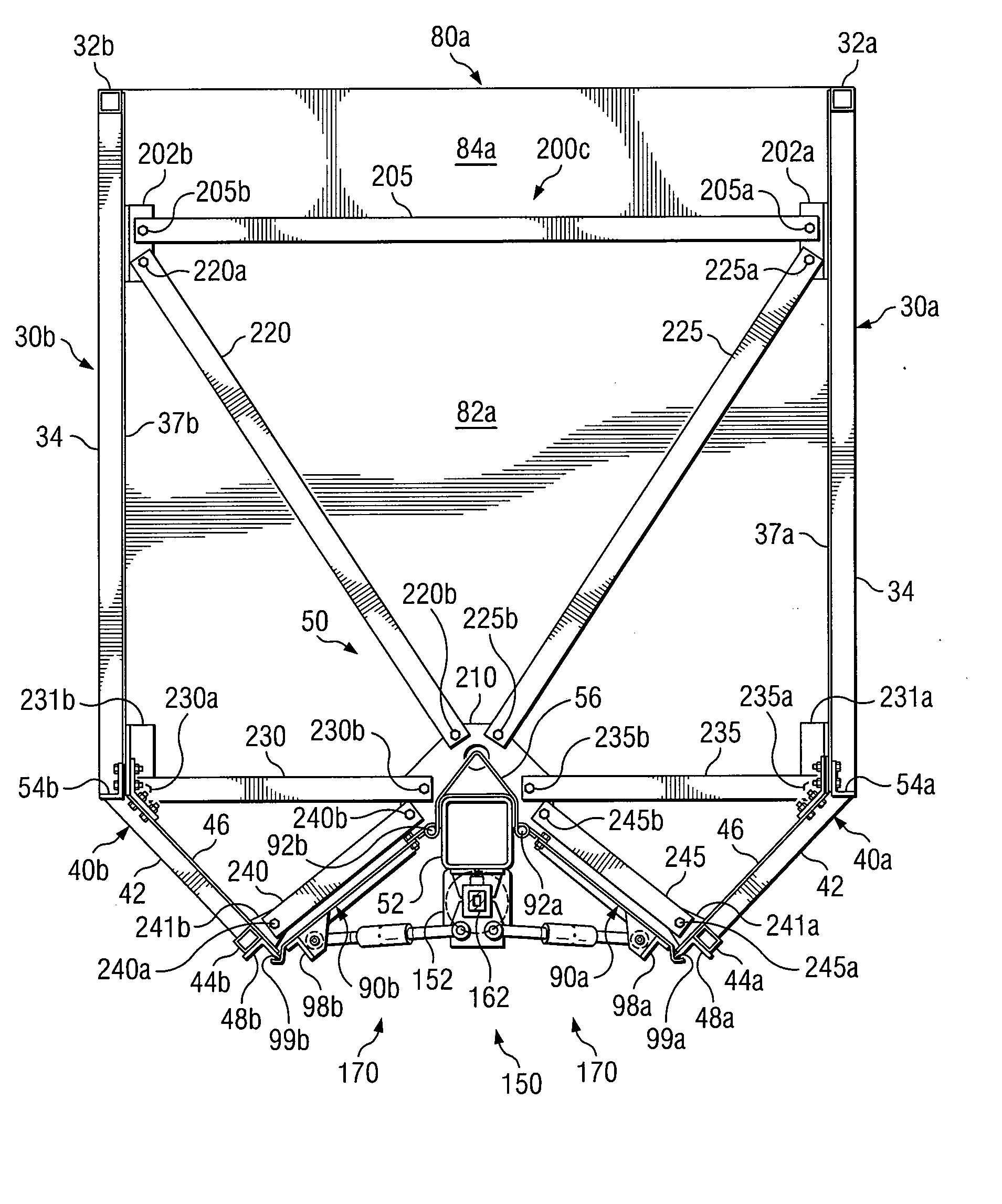
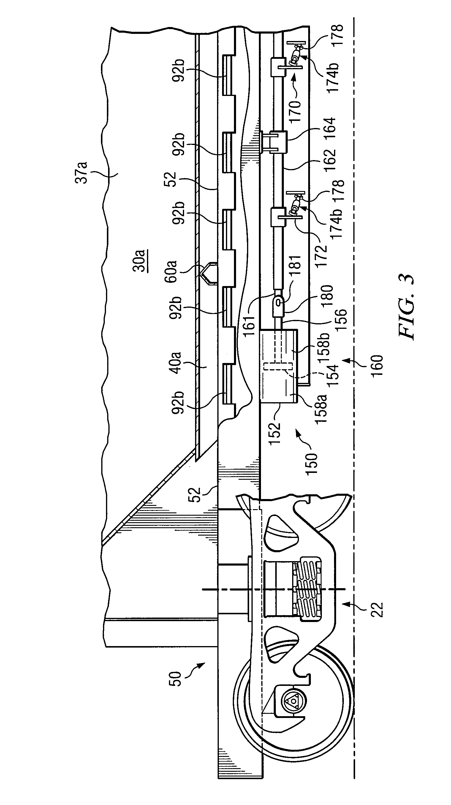
[0014] Discharge control systems incorporating teachings of the disclosure may provide increased mechanical advantage which may allow a relatively small, high speed low torque motor to move a common linkage, associated secondary linkages and discharge doors between their open and closed positions. For some embodiments the common linkage may extend generally parallel with an associated center sill. For other embodiments the common linkage may extend generally perpendicular to an associated center sill. The discharge control system may include over center locking and simplified mechanical adjustments as compared with many prior discharge control systems and operating assemblies for discharge doors and gates.
[0016] Another embodiment may include a railway car having at least one hopper and associated discharge openings formed adjacent to a lower portion or bottom of each hopper. Such railway cars may be efficiently and economically used to transport and unload bulk materials or bulk commodities such as coal at a wide variety of facilities. For example, such railway cars may be satisfactorily used to unload coal at facilities with elevated tracks and bulk commodity handling equipment designed for use with bottom dump hopper cars. Such railway cars may also be satisfactorily used at rotary dump facilities without requiring the use of an associated rotary power dumper.
[0017] Railway cars incorporating teachings of the disclosure may significantly extend the useful life of rotary dump facilities without requiring repair and / or replacement of associated rotary power dumpers. Such railway cars may be economically and efficiently used with two of the most common types of coal unloading facilities, bottom dump facilities and rotary dump facilities. As a result an owner of both bottom dump and rotary dump facilities may save substantial amounts of money by purchasing train sets of hopper cars incorporating teachings of the disclosure which may be satisfactorily used at both types of facilities.
[0019] For some applications a unit train having railway cars with bottom slope sheets, longitudinal discharge openings and a discharge control system incorporating teachings of the disclosure may be unloaded at a rotary dump facility in substantially less than a unit train carrying the same amount of coal in rotary dump cars. The length of time required to unload a unit train with rotary dump cars is often long enough to require at least one crew change during the rotary dump unloading process. A crew may be able to stay on a unit train having railway cars incorporating teachings of the disclosure during the complete unloading process at the same rotary dump facility which reduce costs as compared to unloading a unit train with all rotary dump cars.

Problems solved by technology

Rotary dump unloading facilities are expensive to build and expensive to maintain.
If unloading is slow, each train may be delayed for a substantial period of time adding cost per ton for the associated bulk commodities.

Method used


Image

  • Hopper Cars With One Or More Discharge Control Systems
  • Hopper Cars With One Or More Discharge Control Systems
  • Hopper Cars With One Or More Discharge Control Systems

Examples


Embodiment Construction

[0040] Preferred embodiments of the disclosure and associated advantages may be best understood by referring to FIGS. 1-15B of the drawings. Like numbers may be used for like and corresponding parts of the various drawings.

[0041] Discharge control systems incorporating teachings of the disclosure may be satisfactorily used with a wide variety of railway cars, hopper cars, covered or closed hopper cars, coal cars and ballast cars. For example, various features of the disclosure may be used with closed or covered hopper cars, hopper cars that carry aggregate, ore, grain and other types of bulk lading and ballast cars. Examples of lading carried by covered or closed hopper cars may include, but are not limited to, corn distillers dried grains (DDG), corn condensed distillers solubles (CDS), corn distillers dried grains / solubles (DDGS) and wet distillers grain with solubles (WDGS). Such products may be associated with ethanol production from corn and / or other types of grain.

[0042] Tea...


PUM


Abstract

Hopper cars both open and covered and discharge control systems are disclosed. Each hopper car may include at least one hopper and a center sill which defines in part a longitudinal axis of the hopper car. At least one discharge opening may be formed proximate a lower portion of each hopper. A respective door assembly may be pivotally mounted adjacent to each discharge opening to control the flow of lading from the respective discharge opening. Each discharge control system may include a common linkage and associated secondary linkages operable to move associated door assemblies between a first position and a second position. A power source including a motor, an air cylinder or a hydraulic cylinder may be disposed on the railway car to move the common linkage. For other hopper cars a wayside drive system may be releasably engaged with a capstan operable coupled to the common linkage.

Description

RELATED APPLICATIONS [0001] This application claims the benefit of U.S. Provisional Patent Application Ser. No. 60 / 728,032 filed Oct. 18, 2005 entitled “Hopper Cars With One or More Discharge Control Systems”. [0002] This application is a Continuation-In-Part application from U.S. application Ser. No. 11 / 381,687 filed May 4, 2006 entitled “Railcar With Discharge Control System.”[0003] This application is related to copending Continuation-in-Part application Ser. No. 11 / 548,492, filed Oct. 11, 2006 entitled “Over Center Lock Indicator for Railway Car Door Operation Mechanism” which is a Continuation-In-Part Application from U.S. application Ser. No. 11 / 182,975 filed Jul. 15, 2005 entitled “Safety Latch Lock Indicator For Railcar Door Operation Mechanism,” which claimed the benefit of U.S. Provisional Patent Application Ser. No. 60 / 600,290 filed Aug. 10, 2004.TECHNICAL FIELD [0004] The disclosure is related in general to railway cars and more particularly to hopper cars which discharg...

Claims


Application Information

Patent Timeline
IPC IPC(8): B61D7/00
CPCB61D7/02B61D7/28
Inventor CREIGHTON, GEORGE S.FETTERMAN, D. BRUCEBARRY, ROBERT J.
Owner TRINITY IND INC
Why Eureka
Eureka Blog
Learn More