
Structure and method for simultaneously determining an overlay accuracy and pattern placement error

Active Publication Date: 2007-04-05
GLOBALFOUNDRIES US INC
View PDF17 Cites 51 Cited by
  • Summary
  • Abstract
  • Description
  • Claims
  • Application Information

AI Technical Summary

Benefits of technology

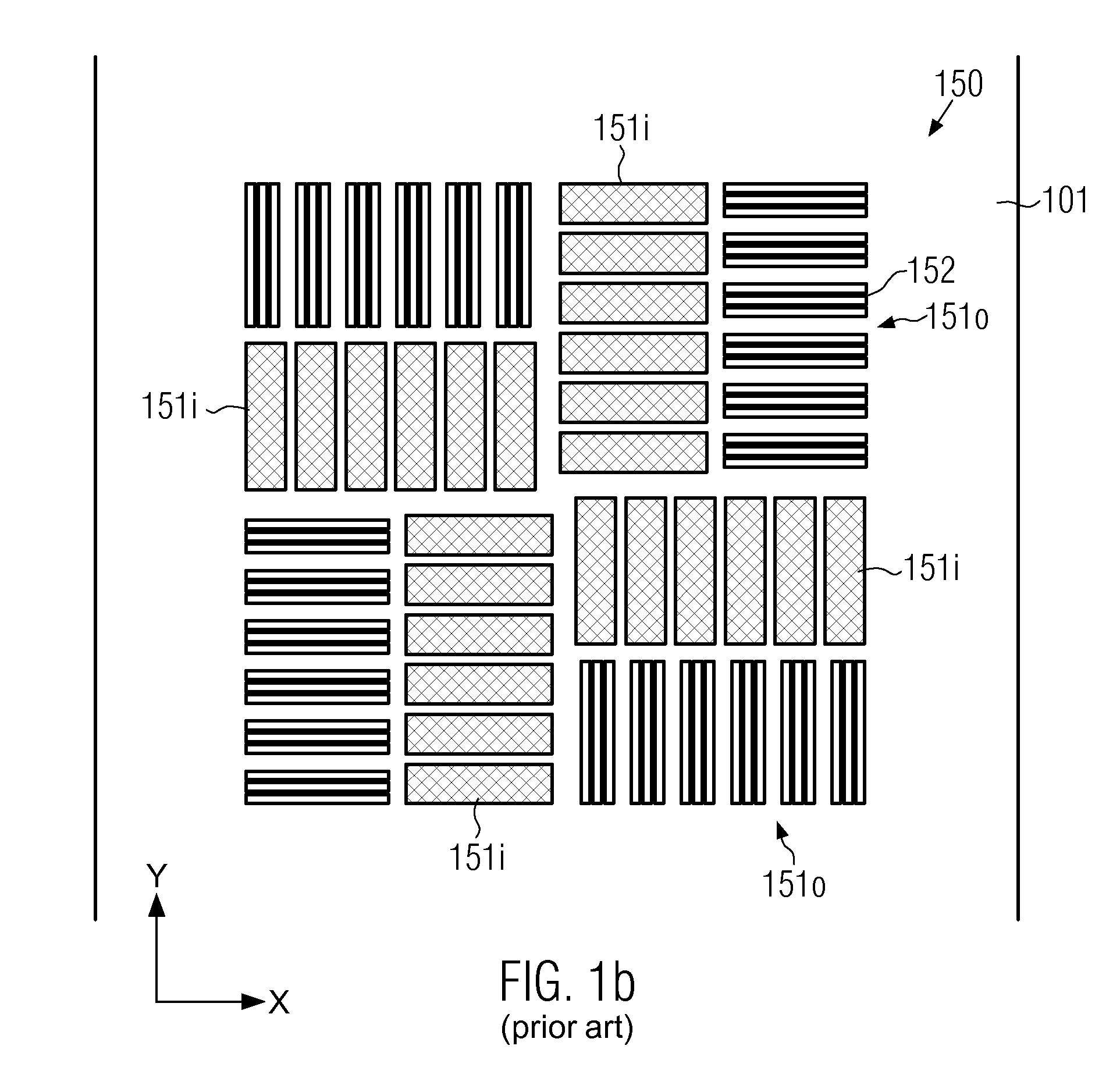
[0017] Generally, the present invention is directed to a technique that enables the evaluation of positional errors during the formation of microstructural features, such as integrated circuits and the like, wherein the amount of space required for providing a corresponding measurement structure may be reduced compared to conventional techniques, while at the same time, in some illustrative embodiments, the amount of position information obtained during a single measurement event may be increased. For this purpose, a stacked measurement structure is provided that includes periodic portions enabling obtaining information about inner-layer positioning errors and inter-layer positioning errors within a predefined measurement site that may be accessed during a single measurement cycle.

Problems solved by technology

These registration tolerances are caused by, for example, a variation of a photoresist image on the substrate due to non-uniformities in such parameters as resist thickness, baking temperature, exposure dose and time and development conditions.
Furthermore, non-uniformities of the etch processes can also lead to variations of the etched features.
In addition, there exists an uncertainty in overlaying the image of the pattern of the current material layer to the etched or otherwise defined pattern of the previously formed material layer while photolithographically transferring the image of the photomask onto the substrate.
Several factors contribute to the ability of the imaging system to perfectly overlay two layers, such as imperfections within a set of masks, temperature differences at the different times of exposure, and a limited registration capability of the alignment tool.
For ever-decreasing feature sizes of microstructures, however, the detection of a displacement, and thus the quantification of an overlay error between both overlay marks, on the basis of edge finding routines may no longer be adequate.
With decreasing feature sizes, however, a discrepancy between overlay characteristics within a single die and the significantly larger structures of the overlay marks, which are typically located in the scribe line of the substrate, may be observed, thereby rendering measurement data obtained from the target in the scribe line less reliable.
Due to the ever-increasing demand on enhanced productivity and reduced manufacturing costs, the dimensions of scribe lines may also be reduced, thereby significantly restricting the available space for any measurement areas within the scribe lines.

Method used


Image

  • Structure and method for simultaneously determining an overlay accuracy and pattern placement error
  • Structure and method for simultaneously determining an overlay accuracy and pattern placement error
  • Structure and method for simultaneously determining an overlay accuracy and pattern placement error

Examples


Embodiment Construction

[0031] Illustrative embodiments of the invention are described below. In the interest of clarity, not all features of an actual implementation are described in this specification. It will of course be appreciated that in the development of any such actual embodiment, numerous implementation-specific decisions must be made to achieve the developers' specific goals, such as compliance with system-related and business-related constraints, which will vary from one implementation to another. Moreover, it will be appreciated that such a development effort might be complex and time-consuming, but would nevertheless be a routine undertaking for those of ordinary skill in the art having the benefit of this disclosure.

[0032] The present invention will now be described with reference to the attached figures. Various structures, systems and devices are schematically depicted in the drawings for purposes of explanation only and so as to not obscure the present invention with details that are we...


PUM


Abstract

The present invention provides a technique for obtaining overlay error and PPE error information from a single measurement structure. This is accomplished by forming periodic sub-structures in at least two different device layers in a single measurement structure, wherein at least one segmented and one non-segmented portion is provided in the two different device layers.

Description

BACKGROUND OF THE INVENTION [0001] 1. Field of the Invention [0002] The present invention relates to the field of fabrication of integrated circuits, and, more particularly, to a method and structures for estimating an overlay accuracy and a pattern placement error (PPE) in forming and patterning stacked material layers used for fabricating microstructural features. [0003] 2. Description of the Related Art [0004] The fabrication of microstructures, such as integrated circuits, requires tiny regions of precisely controlled size to be formed in a material layer of an appropriate substrate, such as a silicon substrate, a silicon-on-insulator (SOI) substrate, or other suitable carrier materials. These tiny regions of precisely controlled size are generated by patterning the material layer by performing photolithography, etch, implantation, deposition, oxidation processes and the like, wherein, typically, at least in a certain stage of the patterning process, a mask layer may be formed o...

Claims


Application Information

Patent Timeline
IPC IPC(8): G01B11/00
CPCG03F7/70633G03F7/70683H01L23/544H01L2924/0002H01L2924/00G03F7/70625
Inventor SCHULZ, BERND
Owner GLOBALFOUNDRIES US INC
Learn More