
Electrode for lithium ion secondary batteries, lithium ion secondary battery using the same, and method for manufacturing the battery

a lithium ion secondary battery and lithium ion battery technology, applied in the direction of cell components, final product manufacturing, sustainable manufacturing/processing, etc., can solve the problems of sudden generation of reaction heat of short circuit, abnormal rise in temperature inside the battery, and easy shrinkage of separation devices made of these materials at high temperatures. , to achieve excellent capacity, charge-discharge characteristics and heat resistan

Active Publication Date: 2007-03-29
PANASONIC CORP
View PDF4 Cites 52 Cited by
  • Summary
  • Abstract
  • Description
  • Claims
  • Application Information

AI Technical Summary

Benefits of technology

[0018] As described hereinbefore, the present invention can provide a lithium ion secondary battery which is safe under internal short circuit conditions or against nail penetration, and which is also excellent in capacity, charge-discharge characteristics and heat resistance.

Problems solved by technology

However, in general, separators made of these materials shrink easily at high temperatures.
If the battery shorts out internally or a sharp-pointed object such as a nail has penetrated through it, there is a sudden generation of reaction heat of the short circuit.
This repeated alternation between the separator shrinkage and the generation of the large amount of reaction heat causes an abnormal rise in the temperature inside the battery.
This causes the battery to decrease in the charge-discharge characteristics or in the capacity.
Furthermore, the porous coating film is intended to reduce exfoliation of the active material, and cannot secure safety against internal short circuit or nail penetration.

Method used


Image

  • Electrode for lithium ion secondary batteries, lithium ion secondary battery using the same, and method for manufacturing the battery
  • Electrode for lithium ion secondary batteries, lithium ion secondary battery using the same, and method for manufacturing the battery
  • Electrode for lithium ion secondary batteries, lithium ion secondary battery using the same, and method for manufacturing the battery

Examples


embodiments

[0089] The present invention will be described more specifically as follows, based on examples.

example 1

(Preparation of the Positive Electrode)

[0090] A positive electrode mixture paste was produced by mixing 3 kg of lithium cobalt oxide having a mean particle diameter of 3 μm; 1 kg of N-methylpyrrolidone solution (solid content: 12 wt%) of polyvinylidene fluoride (#1320 manufactured by Kureha Chemical Industry Co., Ltd.); 90 g of acetylene black; and an appropriate amount of NMP in a double-arm kneader. The paste thus produced was applied on both sides of a 15 μm-thick aluminum foil which was the positive electrode current collector and dried to obtain a positive electrode plate. Next, the positive electrode plate was rolled so that it was 160 μm thick. Then, the rolled positive electrode plate was cut so that it could be inserted into a cylindrical case of size 18650, thereby obtaining a positive electrode.

(Preparation of the Negative Electrode)

[0091] A negative electrode mixture paste was produced by mixing 3 kg of artificial graphite having a mean particle diameter of 20 μm; 7...

example 2

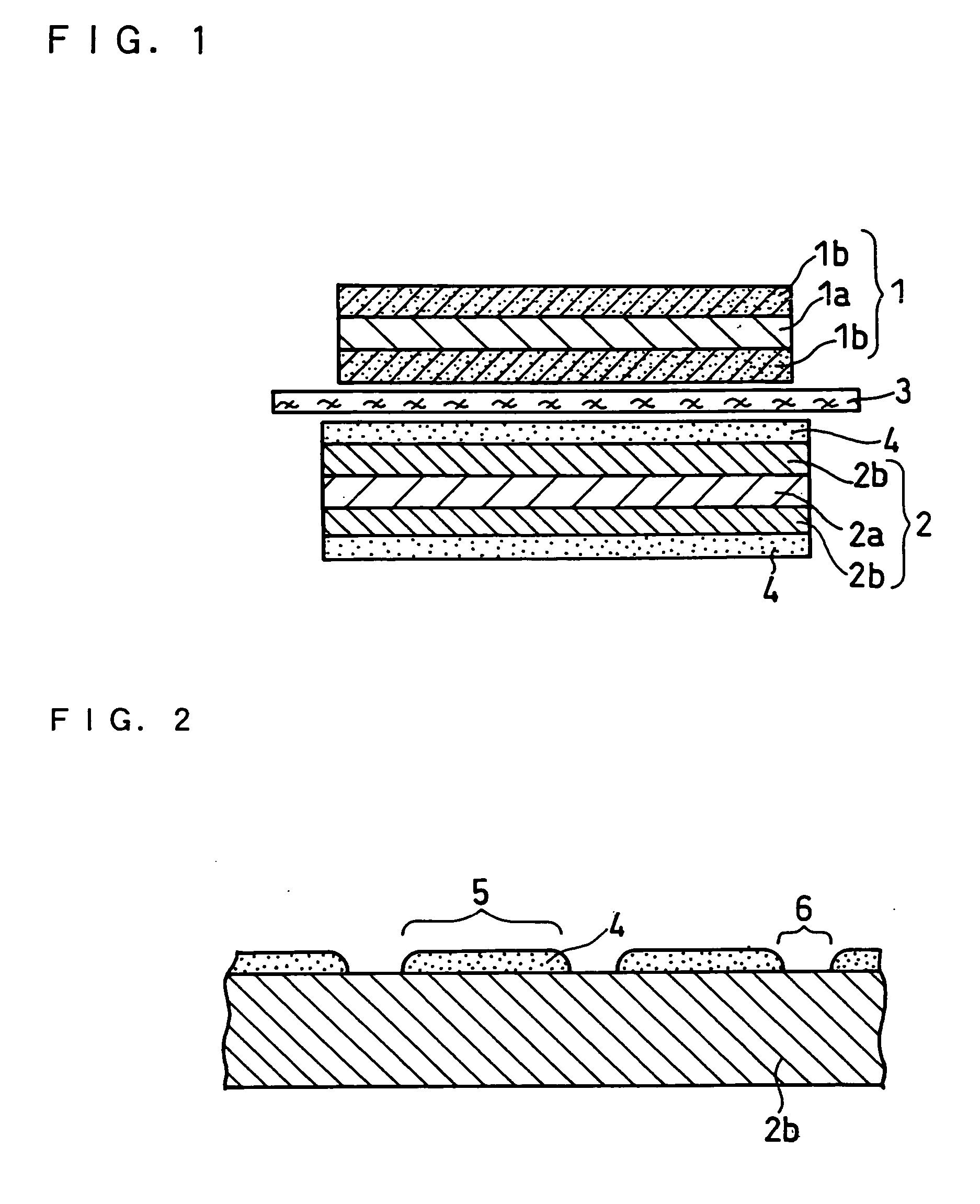
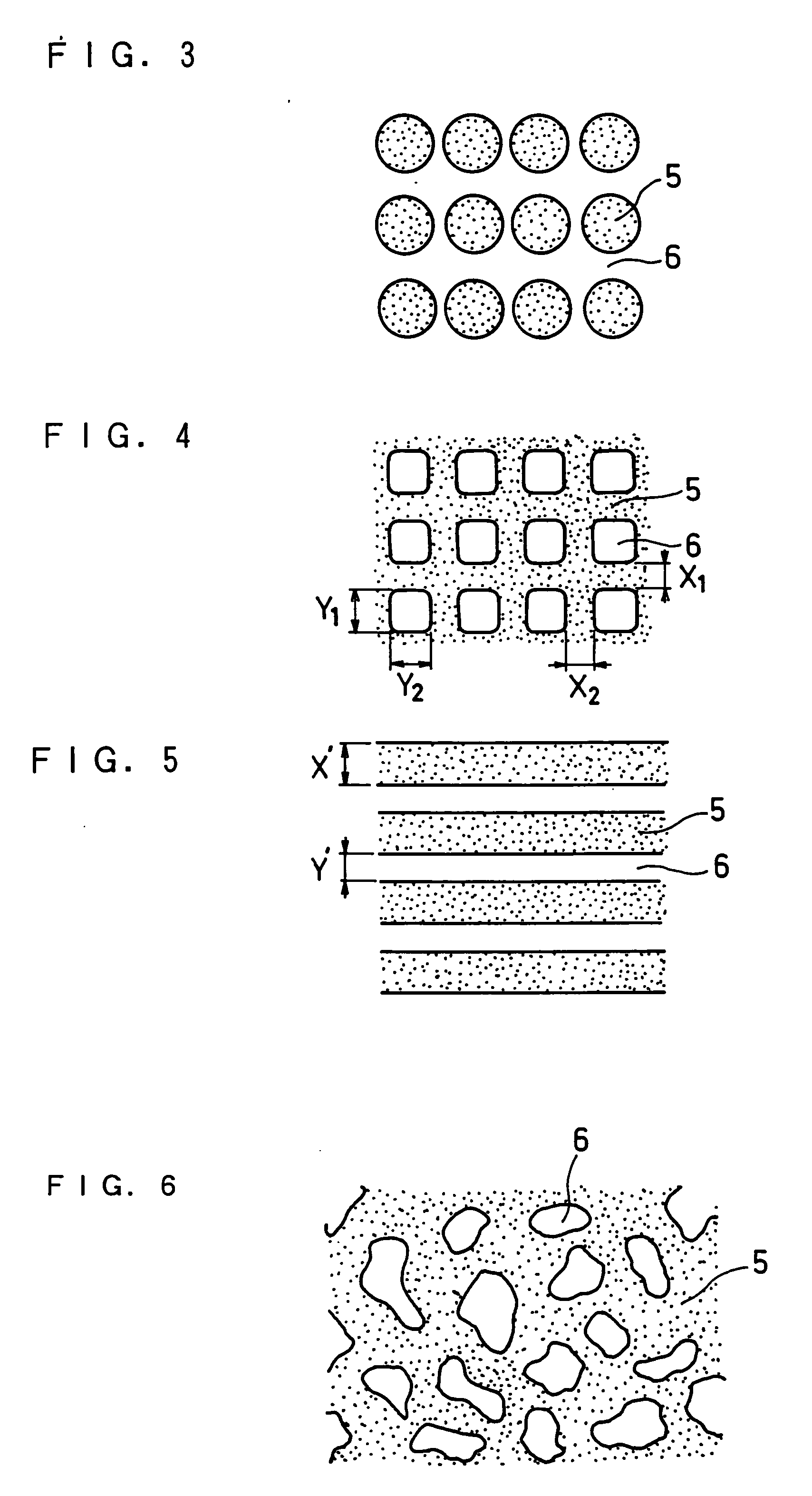
[0100] A lithium ion secondary battery was prepared in the same manner as in Example 1 except that when porous insulating layers with the lattice-like pattern were formed on the surfaces of negative electrode active material layers, the widths X1 and X2 were set to 100 μm, and the widths Y1 and Y2 were set to 400 μm in the lattice-like pattern. The obtained battery was referred to as battery 2. The regions having the porous insulating layers thereon accounted for 36% of the surfaces of both of the negative electrode active material layers.


PUM


Abstract

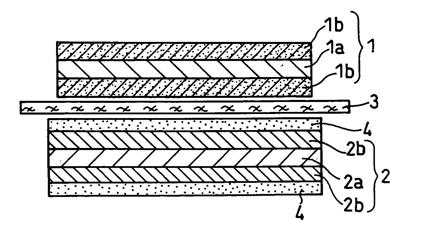
Disclosed is an electrode for lithium ion secondary batteries which includes an active material layer containing active material particles and a porous insulating layer formed on the surface of the active material layer. The porous insulating layer includes an inorganic filler and a resin binder, and the surface of the active material layer has a first region on which the porous insulating layer is formed, and a second region on which the porous insulating layer is not formed. By using such an electrode, a lithium ion secondary battery can have a high capacity, excellent characteristics and improved safety.

Description

TECHNICAL FIELD [0001] The present invention relates to a lithium ion secondary battery excellent in heat resistance and safety under internal short circuit conditions. BACKGROUND ART [0002] An electrochemical battery such as a lithium ion secondary battery is provided between the positive electrode and the negative electrode with a separator which electrically insulates these electrodes and holds electrolyte. Such separators, particularly those in lithium ion secondary batteries, are currently made of microporous film mainly made of polyethylene, polypropylene or the like. [0003] However, in general, separators made of these materials shrink easily at high temperatures. If the battery shorts out internally or a sharp-pointed object such as a nail has penetrated through it, there is a sudden generation of reaction heat of the short circuit. As a result, the separator shrinks to increase the short circuit area so as to generate a larger amount of reaction heat. This repeated alternat...

Claims


Application Information

Patent Timeline
IPC IPC(8): H01M2/16H01M4/04H01M4/13H01M4/131H01M4/139H01M4/1391H01M4/36H01M4/62H01M10/05H01M10/052H01M10/0566H01M10/058
CPCH01M4/04H01M4/0402H01M4/0404H01M4/0414H01M4/0419H01M4/13Y02E60/122H01M4/139H01M4/1393H01M4/366H01M4/621H01M10/0525H01M4/133Y02E60/10Y02P70/50H01G11/26H01G11/50H01G11/86H01G11/06H01M10/058H01M50/491H01M50/446H01M50/59H01M50/417
Inventor IKUTA, SHIGEOOHATA, TSUMORU
Owner PANASONIC CORP
Learn More