
Compact multilayer circuit

a multi-layer circuit and compact technology, applied in the field of circuits, can solve the problems of reducing system reliability, affecting the reliability of the system, and affecting the use of the system, so as to facilitate improved input/output isolation, reduce the form factor required to implement the filter, and enhance the versatility and scalability of the filter

Active Publication Date: 2007-03-22
RAYTHEON CO
View PDF6 Cites 9 Cited by
  • Summary
  • Abstract
  • Description
  • Claims
  • Application Information

AI Technical Summary

Benefits of technology

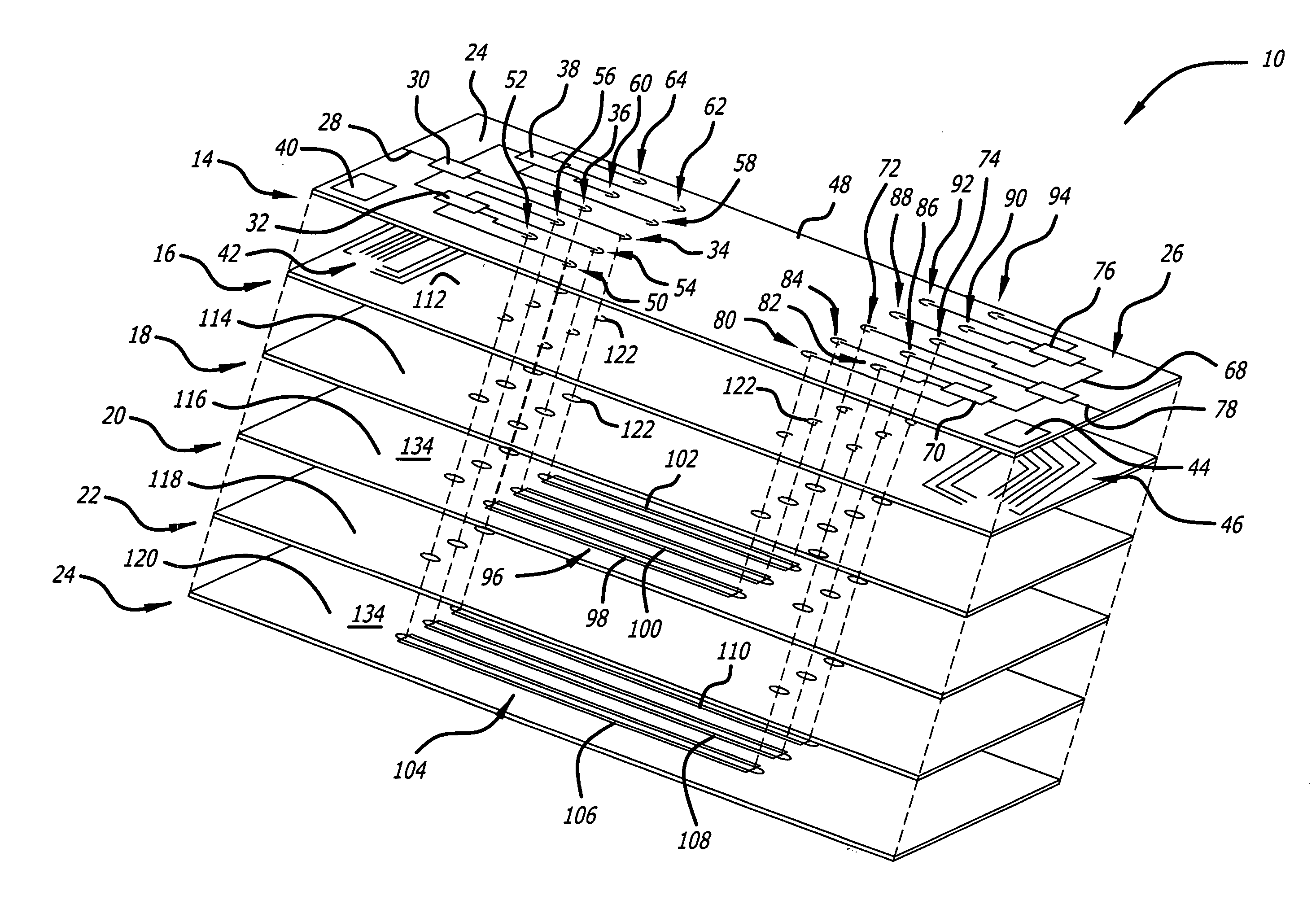
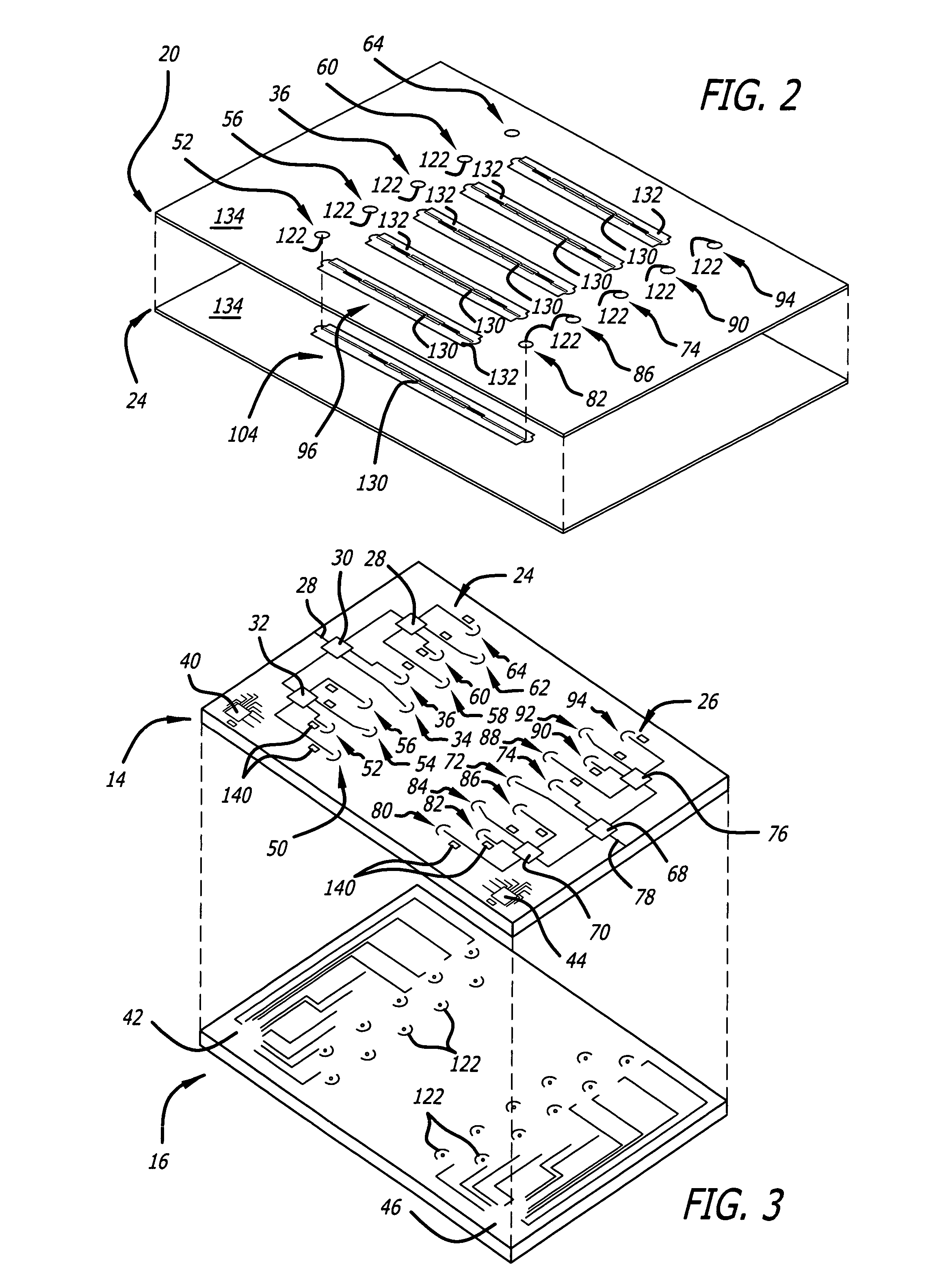
[0011] One embodiment of the present invention is a stacked multilayer microwave filter with several filter elements. The unique positioning of the filter elements between or adjacent to groundplanes facilitates improved input / output isolation and significantly reduces the form factor required to implement the filter. Versatility and scalability of the filter is enhanced via use of unique input and output switching networks. The switching networks can switch a filter input signal to an appropriate layer and accompanying filter element and then selectively output the resulting filtered output signal while achieving minimal interference and maximum electrical isolation between filter input and output terminals. The vertical waveguides that couple the filter elements to the switching networks and that extend through one or more layers of the filter are equipped with special mode-suppression holes that further enhance filter response characteristics.

Problems solved by technology

Compact circuit isolation systems are particularly useful in microwave frequency converters and filter banks, where crosstalk between switches, filters, amplifiers, and signal converters is especially problematic.
Conventionally, microwave frequency-shifter components are individually packaged in expensive double-sided cavitized housing assemblies, which are interconnected via wire, ribbon, and / or solder interconnects.
Such component assemblies are often undesirably large and expensive.
Furthermore, the various interconnects are prone to breakage, which reduces system reliability.

Method used


Image

  • Compact multilayer circuit
  • Compact multilayer circuit
  • Compact multilayer circuit

Examples


Embodiment Construction

[0017] While the present invention is described herein with reference to illustrative embodiments for particular applications, it should be understood that the invention is not limited thereto. Those having ordinary skill in the art and access to the teachings provided herein will recognize additional modifications, applications, and embodiments within the scope thereof and additional fields in which the present invention would be of significant utility.

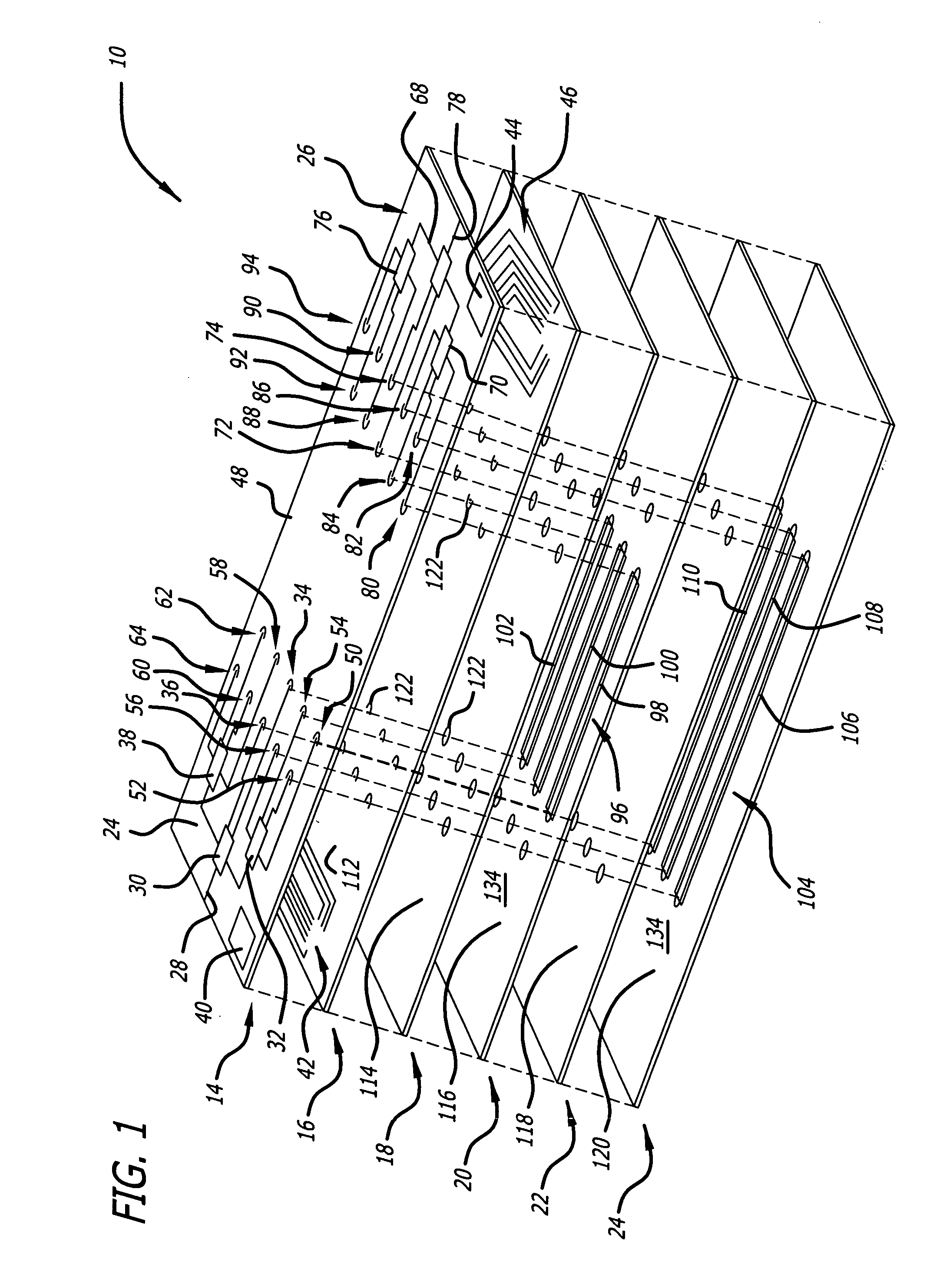
[0018]FIG. 1 is an exploded view of a stacked multilayer programmable microwave filter 10 according to an embodiment of the present invention. For clarity, various well-known components, such as power supplies, antennas, and so on, have been omitted from the figures. However, those skilled in the art with access to the present teachings will know which components to implement and how to implement them to meet the needs of a given application.

[0019] The stacked programmable microwave filter 10 includes, from top to bottom, a switchi...


PUM


Abstract

A compact multilayer signal processing system. In the illustrative embodiment, the system is adapted for use with microwave signals. The system includes a first mechanism for receiving an input signal and selectively routing the input signal onto a first signal path. A second mechanism routes the input signal along the first signal path vertically through one or more layers to a first circuit component. The first circuit component outputs an adjusted signal in response to receipt of the input signal. A third mechanism directs the adjusted signal to the output of the system. In a specific embodiment, the one or more layers include one or more groundplane layers. In this embodiment, the first mechanism includes an input switching network in communication with a controller. The switching network is positioned on a switching layer and communicates with one or more controllers to facilitate selectively switching the input signal onto one of plural input signal paths. The second mechanism further includes a first input waveguide that extends from the input switching network vertically through at least one groundplane layer and to an input end of the first circuit component. The third mechanism includes a first output waveguide extending from an output end of the first circuit component, vertically through at least one groundplane layer to an output switching network disposed on the switching layer. In the specific embodiment, the circuit layer includes plural circuit components that are coupled to respective input waveguides and output waveguides that extend vertically through the first groundplane layer to the input switching network and the output switching network, respectively.

Description

BACKGROUND OF THE INVENTION [0001] 1. Field of Invention [0002] This invention relates to circuits. Specifically, the present invention relates to systems and methods for packaging and isolating circuits, such as microwave frequency converter circuits. [0003] 2. Description of the Related Art [0004] Circuit isolation and packaging systems are employed in various demanding applications including microwave filter banks. Such applications demand compact packaging that minimizes electrical interference between components. [0005] Compact circuit isolation systems are particularly useful in microwave frequency converters and filter banks, where crosstalk between switches, filters, amplifiers, and signal converters is especially problematic. Conventionally, microwave frequency-shifter components are individually packaged in expensive double-sided cavitized housing assemblies, which are interconnected via wire, ribbon, and / or solder interconnects. Such component assemblies are often undesir...

Claims


Application Information

Patent Timeline
Patent Type & Authority Applications(United States)
IPC IPC(8): H01P1/10
CPCH01P1/20345H01P1/127H01P1/203
Inventor DALCONZO, LAWRENCEMOYE, CHRISTOPHER A.BARRIENTOS, EDUARDO D. JR.DRAPEAU, DAVID J.CRNKOVICH, MICHAEL T.AKALE, TAMRAT
Owner RAYTHEON CO
Learn More