Image encoding apparatus and image encoding method
a technology of image encoding and encoding apparatus, which is applied in the direction of code conversion, color television with bandwidth reduction, television systems, etc., can solve the problems of insufficient prevention, and deterioration of image quality
- Summary
- Abstract
- Description
- Claims
- Application Information
AI Technical Summary
Benefits of technology
Problems solved by technology
Method used
Image

Examples
first embodiment
[0024] An embodiment will be described hereinbelow with reference to the drawings. The present invention is not limited to respective embodiments provided below, and can be utilized in various combinations.
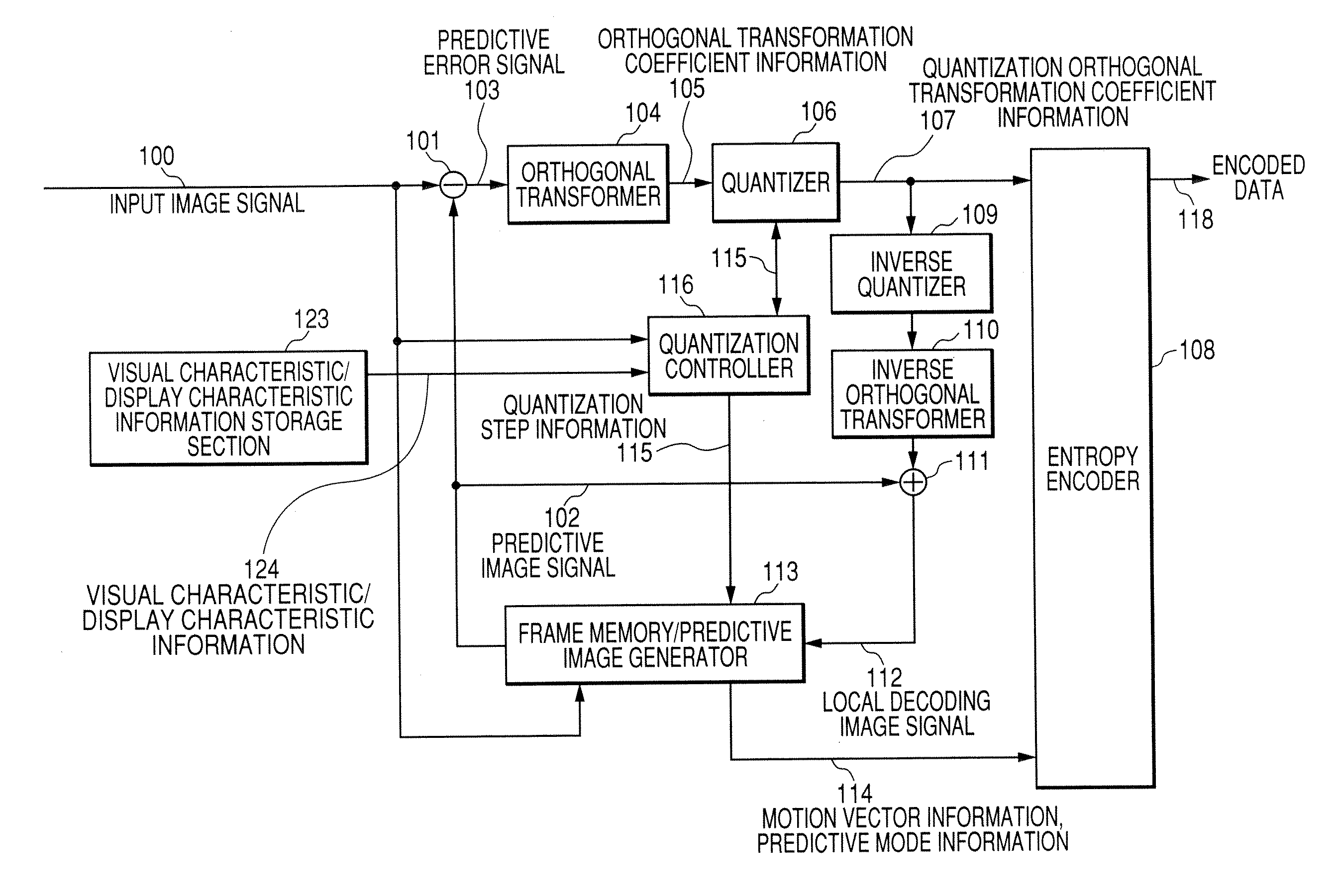
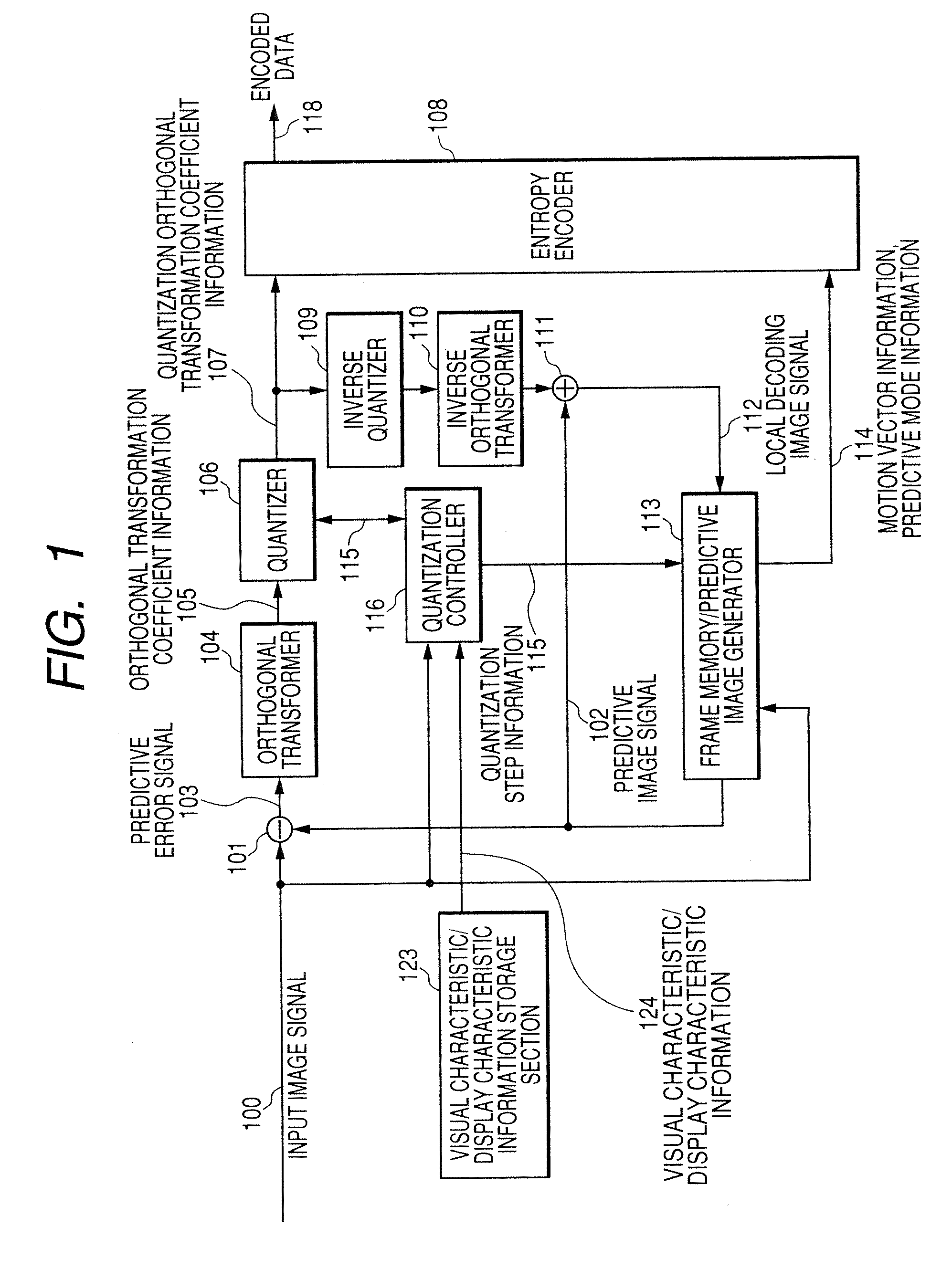
[0025]FIG. 1 is a block diagram showing the configuration of an image encoder for encoding a motion picture according to a first embodiment.
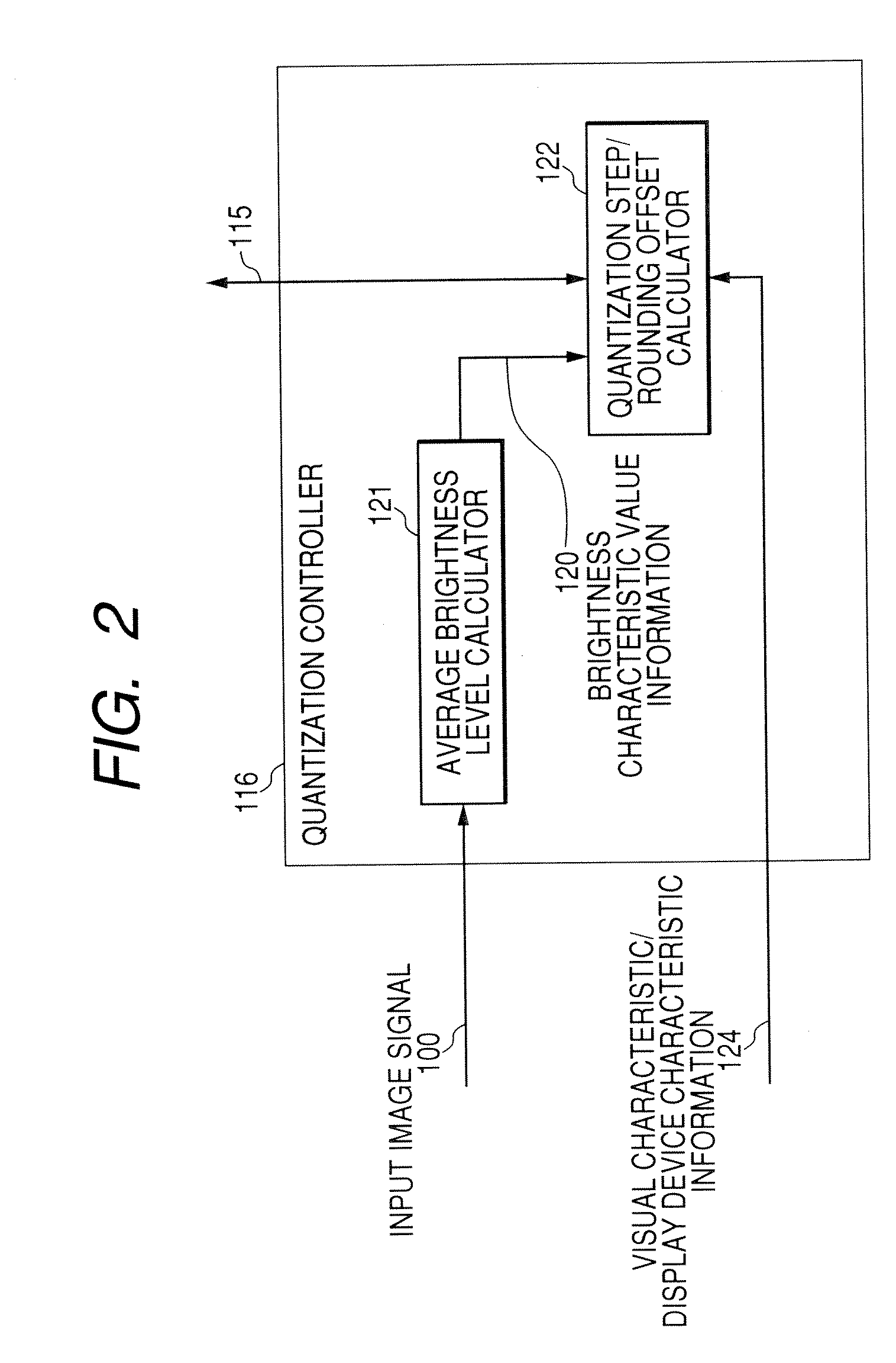
[0026] As shown in FIG. 1, this image encoder has a subtractor 101, an orthogonal transformer 104, a quantizer 106, an entropy encoder 108, an inverse quantizer 109, an inverse orthogonal transformer 110, an adder 111, a frame memory / predictive image generator 113, a quantization controller 116, and a visual characteristic / display characteristic information storage section 123.
[0027] First, a motion picture signal is input on, e.g., a per-frame basis, as an input image signal 100 for the image encoder. The subtractor 101 determines a difference between the input image signal 100 and a predictive image signal 102, to thus generate a predicti...
second embodiment
[0065]FIG. 5 is a block diagram of the entire image encoder according to a second embodiment. Although the present embodiment is essentially analogous to the first embodiment, the present embodiment differs from the first embodiment in that the visual characteristic parameter and the display characteristic parameter can be input from the outside to the visual characteristic / display characteristic information storage section 123. Operation of the quantization controller 116 is essentially analogous to the operation of the quantization controller 116 of the first embodiment. However, they differ from each other in that the values, which have been input from the outside and stored in the visual characteristic / display characteristic information storage section 123, are used as the visual characteristic / display characteristic information 124 (α, γ, Yjnd, Ymin, Ymax) used in mathematical Expression 7, i.e., a formula pertaining to the range of modification to the quantization step.
[0066]...
third embodiment
[0076] In the present embodiment, the block diagram of an entire image encoder is analogous to those of the first and second embodiments. However, the present embodiment differs from the first and second embodiments in that selection is performed in accordance with the number of DCT coefficients obtained when the quantization controller 116 has quantized a macro block whose quantization step is to be modified.
[0077]FIG. 7 is a flowchart showing an example operation of the quantization controller 116 of the present embodiment.
[0078] Operations pertaining to S301 to S303 and operation pertaining to S305 are the same as their counterparts in the first embodiment, where a value of the range of modifications to the quantization step is determined.
[0079] Next, in step S307, a determination is made as to whether or not the range of modification to the quantization step assumes a negative value. When the range of modification assumes a negative value, processing proceeds to step S308. Qu...
PUM
 Abstract
Description
Claims
Application Information
 - R&D
- Intellectual Property
- Life Sciences
- Materials
- Tech Scout
- Unparalleled Data Quality
- Higher Quality Content
- 60% Fewer Hallucinations
Browse by: Latest US Patents, China's latest patents, Technical Efficacy Thesaurus, Application Domain, Technology Topic, Popular Technical Reports.
© 2025 PatSnap. All rights reserved.Legal|Privacy policy|Modern Slavery Act Transparency Statement|Sitemap|About US| Contact US: help@patsnap.com