Vehicle-use generator
a generator and vehicle-use technology, applied in the direction of electric generator control, synchronous generators, dynamo-electric machines, etc., can solve the problems of slow generation speed and difficulty in keeping the generation voltage at the target regulation voltage, so as to improve the output control responsiveness of vehicle-use generators, reduce field current, and suppress the effect of field coil temperature ris
- Summary
- Abstract
- Description
- Claims
- Application Information
AI Technical Summary
Benefits of technology
Problems solved by technology
Method used
Image
Examples
second embodiment
[0053]FIG. 5 is a schematic cross-sectional view of a vehicle-use generator according to a second embodiment of the invention.
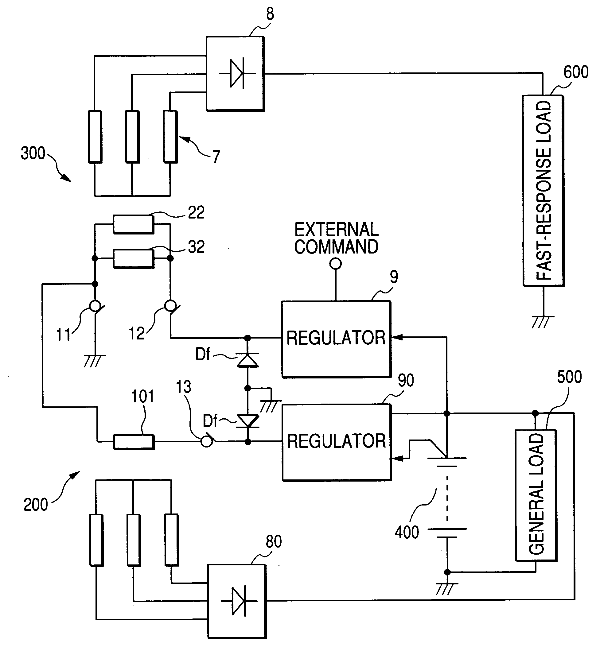
[0054] The second embodiment has a three-throw tandem rotor structure in which another Lundell type rotor core 100 is added to the rotor cores 21, 31 shown in FIG. 1. In FIG. 5, the reference numeral 101 denotes a field coil wound around the Lundell type rotor core 100, 60 denotes a stator core, 70 denotes a stator coil wound around the stator core 60. Here, the stator-rotor pair constituted by the Lundell type rotor cores 21, 31, the field coils 22, 32, the stator core 6, and the stator coil 7 is designated as a first stator-rotor pair 300, and the stator-rotor pair constituted by the Lundell type rotor core 100, the field coil 101, the stator core 60, and the stator coil 70 is designated as a second stator-rotor pair 200.
[0055]FIG. 6 is a circuit diagram showing an electrical structure of the vehicle-use generator of the second embodiment. As shown in thi...
third embodiment
[0057]FIG. 7 is a circuit diagram showing an electrical structure of a vehicle-use generator according to a third embodiment of the invention.
[0058] The third embodiment is different from the first embodiment in that a chopper type DC-DC converter 900 is provided for stepping up the voltage of the battery 400, and the field coils 22, 32 are applied with this stepped up voltage in the third embodiment. The DC-DC converter 900 is constituted by transistors 91, 92, and a reactor 93 for accumulation of magnetic energy.
[0059] The transistors 91, 92 of the DC-DC converter 900 are turned on and off at a certain frequency by the regulator 9. The voltage-step-up ratio of the DC-DC converter 900 is determined by the duty ratios of these transistors. When the transistor 92 is turned on, and the transistor 91 is turned off, magnetic energy is accumulated in the reactor 93. Subsequently, when the transistor 92 is turned off, and the transistor 91 is turned on, the field coils 22, 32 are applie...
fourth embodiment
[0061]FIG. 8 is a circuit diagram showing an electrical structure of a vehicle-use generator according to a fourth embodiment of the invention. The fourth embodiment is different from the third embodiment shown in FIG. 7 in that a vibration reduction circuit 2000 and an electric double-layer type smoothing capacitor 3000 having a large capacitance are additionally provided in the fourth embodiment.
[0062] The vibration reduction circuit 2000 is for reducing an engine vibration and a vehicle vibration caused by the engine vibration by controlling the phase of the power generation torque of the vehicle-use generator coupled to the engine through a belt-pulley mechanism which enables torque transmission therebetween. More specifically, the vibration reduction circuit 2000 controls the power generation torque such that the power generation torque and the engine torque vary in opposite phase to each other.
[0063] When the vibration reduction circuit 2000 receives a signal from outside in...
PUM
 Abstract
Description
Claims
Application Information
 - R&D
- Intellectual Property
- Life Sciences
- Materials
- Tech Scout
- Unparalleled Data Quality
- Higher Quality Content
- 60% Fewer Hallucinations
Browse by: Latest US Patents, China's latest patents, Technical Efficacy Thesaurus, Application Domain, Technology Topic, Popular Technical Reports.
© 2025 PatSnap. All rights reserved.Legal|Privacy policy|Modern Slavery Act Transparency Statement|Sitemap|About US| Contact US: help@patsnap.com


