Eureka AIR delivers breakthrough ideas for toughest innovation challenges, trusted by R&D personnel around the world.

Apparatus for treating fluid streams

a technology for fluid streams and apparatuses, applied in the direction of fluid removal, insulation, borehole/well accessories, etc., can solve the problems of significant amount of heat energy being lost to the surrounding environment and non-productive parts of the well, poor heat transfer characteristics, and significant energy loss to the surrounding environment, so as to improve the efficiency of fluid stream delivery, reduce operating costs, and improve the effect of fluid stream production

Inactive Publication Date: 2007-03-15
AMP ELEVATOR GROUP
View PDF3 Cites 32 Cited by
  • Summary
  • Abstract
  • Description
  • Claims
  • Application Information

AI Technical Summary

Benefits of technology

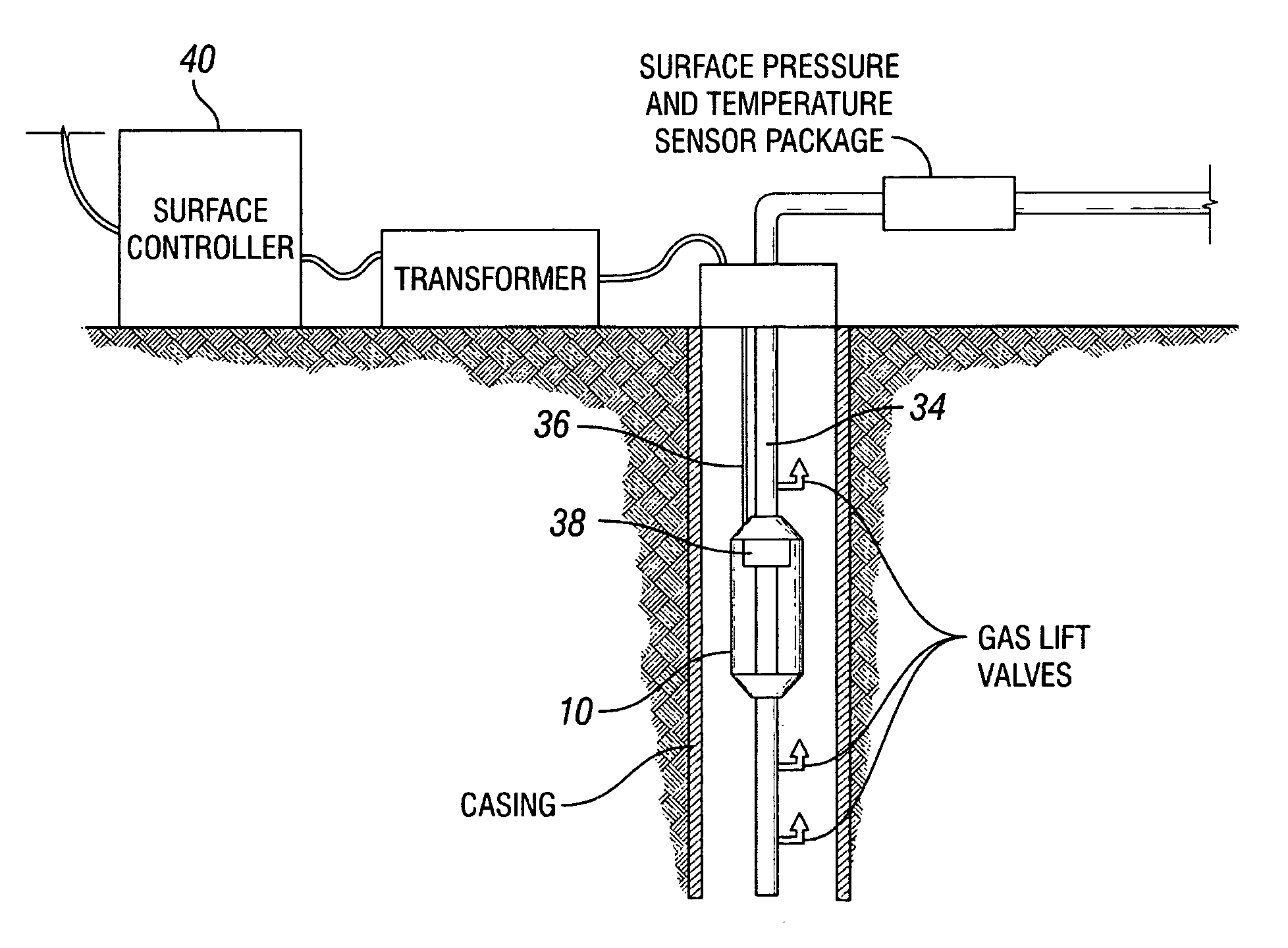
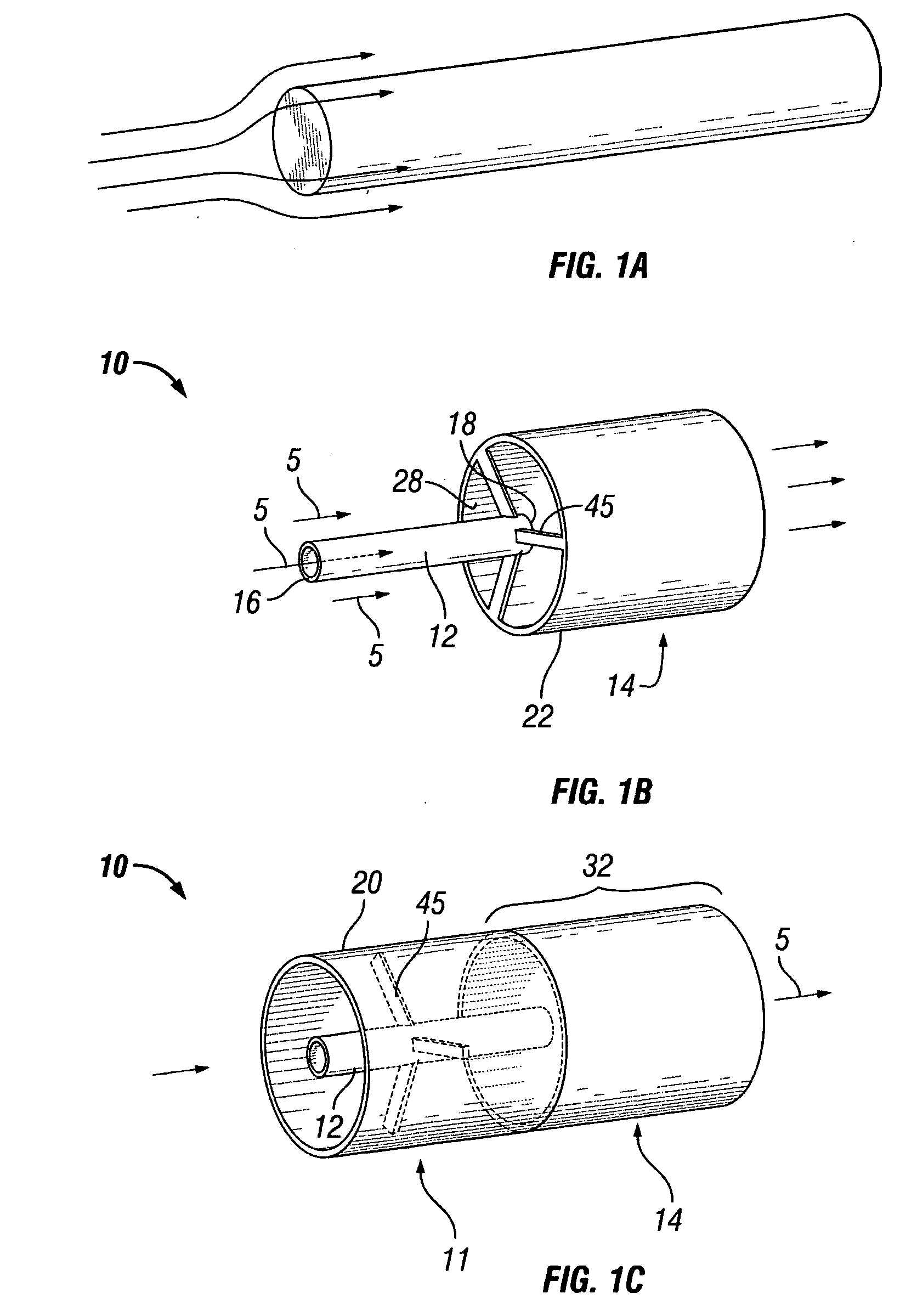
[0011] It is an object of this invention to provide an apparatus and methods of use that regulate and preferably provide regulated increases in the temperature of a hydrocarbon stream produced from an oil and gas well or to preferably increase the temperature of fluid streams introduced into a well for instance light oil, diluents, or any other liquid including water. It is an object of the invention to enhance the efficiency of fluid stream delivery to the surface by conventional lift methods or in a free flowing well, lower operating costs and / or higher producing rates. The invention also preferably features surface controls that assist with regulating, sensing and measuring fluid stream temperature, pressure, rate and other parameters of the lifting system. It is an object of this invention to provide an apparatus and methods of use that regulate temperature to a hydrocarbon fluid stream produced from an oil or gas well or to regulate temperature of fluid streams introduced into a well, for instance in injection operations. It is an object of this invention to enhance efficiency of stream delivery to the surface by conventional lift methods or in a free flowing well, at lower operating costs and at higher producing rates. It is an object of the invention to provide these and other benefits by and through methods and use of an apparatus preferably featuring uniquely adapted heating chamber(s), mixing chamber(s) and preferable shrouds as further shown and described in the specification and figures of this application. The apparatus may be located at a plurality of locations along a wellbore and is preferably used to regulate temperatures of fluids flowing from a reservoir to the surface, or alternatively from the surface to the reservoir. The invention also preferably features surface controls that assist with regulating, sensing and measuring fluid temperatures.
[0012] Another preferable object is to produce an apparatus that can cost effectively provide regulated temperature increases downhole to a fluid stream injected into a well (injection or production) from the surface in order to clean up the near well bore completion zone and / or remove or decrease skin damage in order to restore or increase well productivity. Another preferable object of this invention is to produce an apparatus that can cost effectively provide regulated temperature increases downhole to a fluid stream injected into an injection well located in a hydrocarbon producing field from the surface in order to improve hydrocarbon delivery from the reservoir to one or more producing wells.
[0013] Another preferable object of this invention is to provide apparatus that may be permanently installed in a producing hydrocarbon well that can cost effectively provide regulated temperature increases to a fluid stream downhole, whether said fluid stream is injected from the surface into a producing well, or alternatively produced from a well. It is well understood that injecting hot water, oil or steam from the surface using an injection well into a hydrocarbon reservoir can lower the viscosity of deposits in the reservoir and improve delivery to nearby producing wells. Since significant temperature losses occur in this fluid stream from any surface heating facility to the reservoir, it is clear that providing heat to the fluid stream downhole near the target producing zone in the reservoir will result in energy savings.

Problems solved by technology

These techniques often have poor heat transfer characteristics and can lead to significant amounts of energy being lost to the surrounding environment and to non-productive parts of the well.
For instance, with resistance heating cables, which are strapped to the production tubing string to provide heat to the fluid stream inside the tubing during production, a central problem is created because a significant part of the cable is exposed to the surrounding well bore environment.
This results in a significant amount of heat energy being lost to the surrounding environment, where it is of little value.
Another problem with resistance heating cable systems is that it is extremely difficult to make certain that the heating cable maintains an unbroken contact with the production tubing since gaps where there is no contact will appear at locations where the cable does not lie flat on the tubing.
These air gaps significantly lower the efficiency of heat transfer between the cable and the tubing string.
Yet another problem with common resistance heating cable systems is that a significant portion of the heat energy, which is delivered to the production tubing, is used to heat the tubing and not the fluid inside.
Finally, since none of the heat provided by resistance cable systems is to the fluid below the pump intake, fluid viscosity through the pump is unchanged and there is no benefit to pump performance or efficiency.
The main problem with this configuration is that they have poor heat transfer characteristics due to a lack of fluid flow through the center resulting in internal and surface element temperatures that are significantly higher.
The main result is poor efficiency in the heat transfer process.
In order to compensate for this poor efficiency, these types of tools must operate with significantly higher surface temperatures, which can lead to coke formation on the heated surfaces.
This build-up of coke further limits heat transfer and exacerbates the problem.
This means that a significant portion of the heat energy that they provide is lost to the surrounding environment with limited results.
The main problem with induction heaters is that the clearance between the powered induction coil and the casing or tubing must be very small in order to maintain minimum levels of energy efficiency.
Since the induction coil in most designs is located in the path of the production fluid stream, they often add significantly to pressure losses in the fluid stream defeating their purpose.
In addition, placing an electrical current inside any component of a producing well such as the tubing or casing will significantly increase the corrosion rate and may cause premature failure.
The main problem with steam or hot oil injection products is that significant levels of heat energy are lost in these processes to non-productive parts of the well such as the casing, annulus and portions of the earth in contact with the casing that are not a part of the reservoir.
In addition, the surface infrastructure required for permanent steam injection takes considerable space on the surface making this application undesirable in most offshore applications and populated areas.

Method used


Image

  • Apparatus for treating fluid streams
  • Apparatus for treating fluid streams
  • Apparatus for treating fluid streams

Examples


Embodiment Construction

[0041] The present application relates to an apparatus suitable for treating fluid streams by: [0042] (a) transferring temperature increases to fluid streams, whether the fluid stream is produced downhole, or is injected from the surface; [0043] (b) regulating, and increasing temperature of the downhole fluid stream; [0044] (c) being installed downhole in a wellbore whether permanently or temporarily; [0045] (d) transferring temperature increases to fluid flowing in any direction; and [0046] (e) reaching and maintaining a selected fluid stream viscosity.

[0047] The present application also relates to a system suitable for: [0048] (a) recording downhole pressures and temperatures; [0049] (b) recording surface pressures and temperatures; [0050] (c) recording and monitoring power usage of the apparatus during treatment of a fluid stream; and [0051] (d) communicating surface and downhole fluid stream temperature and pressure and other parameters to the surface in order to monitor the ef...


PUM


Abstract

An apparatus and method for increasing and regulating temperature, pressure and fluid viscosities of fluid streams found in oil and gas production. Applicant's apparatus regulates and increases fluid temperatures, by and through improved heating apparatus, which may be placed at one or more locations along a wellbore surface flow line, or subsea flow line. The apparatus preferably either heats fluids flowing from the reservoir to the surface, or alternatively, can heat fluids injected from the surface into the reservoir.

Description

CROSS-REFERENCE TO RELATED APPLICATIONS [0001] The present application claims the benefit of the filing date of U.S. Provisional Patent Application Ser. No.60 / 642,588 filed Jan. 11, 2005. STATEMENT REGARDING FEDERALLY SPONSORED RESEARCH OR DEVELOPMENT [0002] Not applicable.FIELD OF THE APPLICATION [0003] The application relates generally to an apparatus for treating a fluid stream flowing inside a pipe or tubing. BACKGROUND OF THE INVENTION [0004] It is understood in oil and gas production that heating a downhole fluid stream can (a) lower fluid stream viscosity, (b) reduce tubing friction losses, (c) reduce wellhead pressure requirements, (d) reduce or otherwise eliminate the formation of emulsions, and (e) improve pump efficiency, which in turn, can reduce the energy required to deliver a fluid stream to the surface from downhole and can also reduce the load placed on lift system components. It is also known that maintaining the temperature of a fluid stream above the cloud point ...

Claims


Application Information

Patent Timeline
Patent Type & Authority Applications(United States)
IPC IPC(8): E21B43/00
CPCE21B36/04E21B43/25E21B37/00
Inventor PANKRATZ, RONALD ELRICKKUSLITSKY, LENNYBRATUSHKIN, ANDREWLESHCHENYUK, LEONID
Owner AMP ELEVATOR GROUP
Why Eureka
Eureka Blog
Learn More