
Anti-dazzling film

a technology of anti-glare and film, applied in the direction of polarising elements, instruments, ways, etc., can solve the problems of uneven layer thickness uneven surface hardness, etc., and achieve the effect of satisfying surface hardness

Active Publication Date: 2007-03-08
DAI NIPPON PRINTING CO LTD +1
View PDF4 Cites 22 Cited by
  • Summary
  • Abstract
  • Description
  • Claims
  • Application Information

AI Technical Summary

Benefits of technology

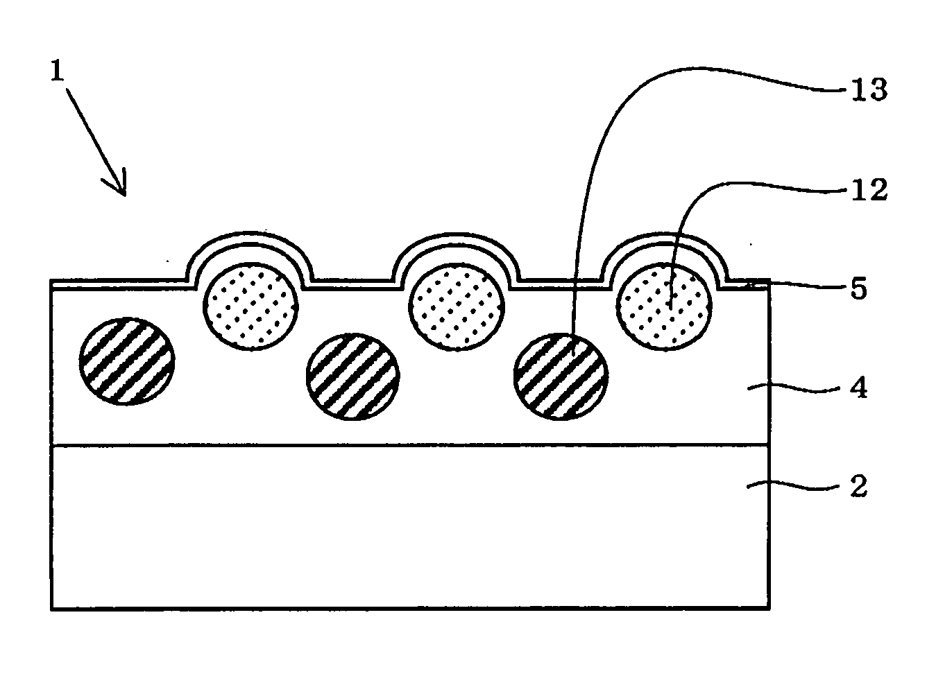
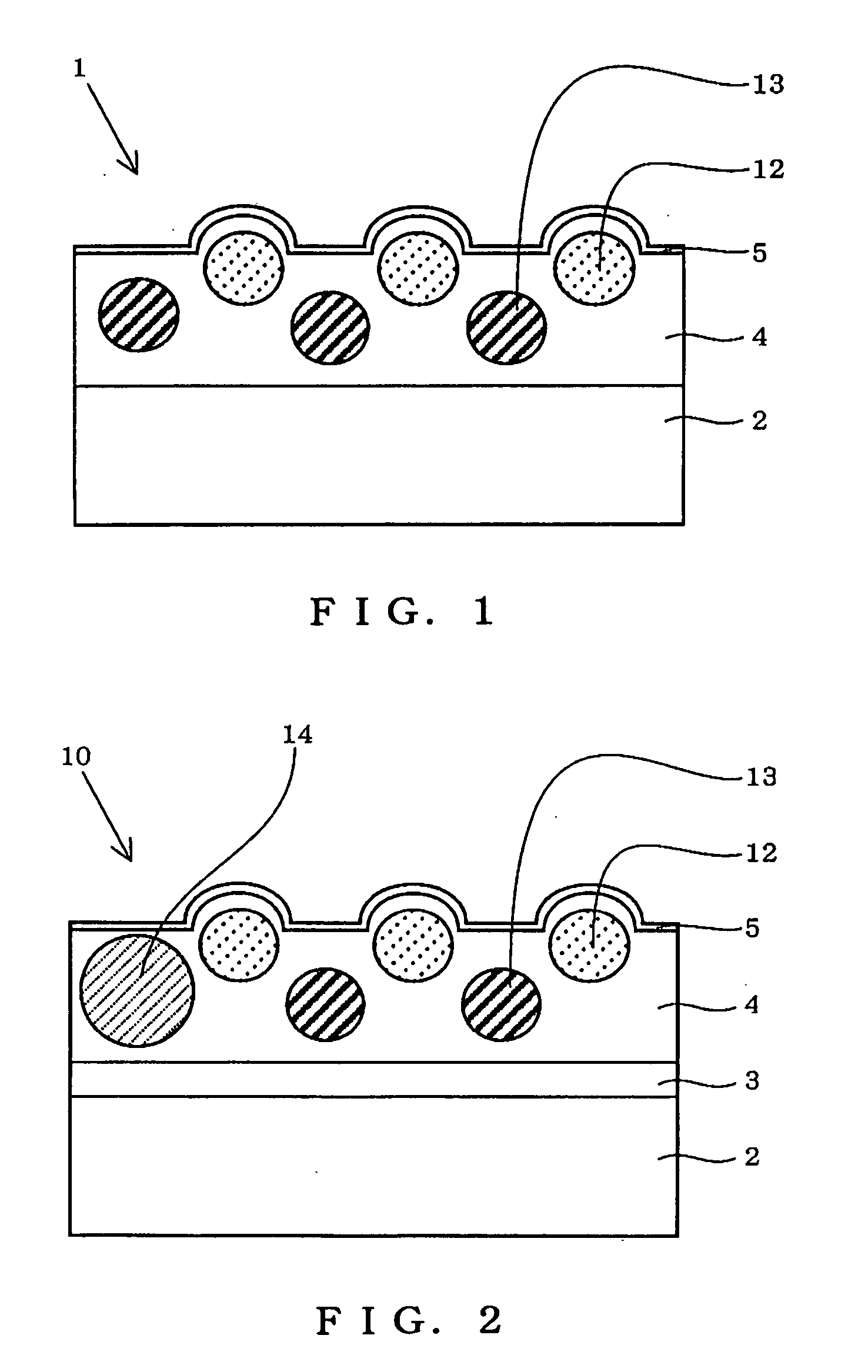
The present invention provides an anti-dazzling film and an antireflection film that can meet market demands for increased area, homogeneous properties, and lowered cost while maintaining good scratch resistance. The anti-dazzling film comprises a triacetylcellulose film and an anti-dazzling layer that can provide a high-speed coating and meet market demands for high-speed coating. The anti-dazzling layer comprises a light transparent resin, plastic light transparent fine particles, and a leveling agent. The low-refractive index layer is provided on the anti-dazzling layer and can meet market demands for an increased area and homogeneous properties. The anti-dazzling film and antireflection film can provide good planar appearance and evenness of coated face during high-speed coating.

Problems solved by technology

In the production of the antireflection film, as compared with films formed by a dry process typified by vapor deposition and sputtering, basically, the formation of a film by a wet process using coating is disadvantageous in that, although there is a potential that low-cost production could be realized, high-speed coating is likely to cause uneven flow, uneven drying, or coating streaks by entrained air and drying air, and, consequently, is likely to cause uneven layer thickness.
Thus, maintaining and improving the homogeneity required of the antireflection film are very difficult, leading to a serious problem.
Since, however, the surface free energy of a coating film after drying is reduced, stacking of a low-refractive index layer indispensable to the antireflection film onto the coating face weakens the adhesion at the interface.
As a result, breaking is likely to occur by external force, disadvantageously leading to a problem that only antireflection films having poor scratch resistance can be produced.
In Japanese Patent Laid-Open No. 53878 / 2003, however, there is no description on an improvement in scratch resistance.
Further, the addition of a silicone leveling agent to an anti-dazzling layer followed by stacking of a low-refractive index layer indispensable to the antireflection film, as with the above case, is disadvantageous in that, although the leveling effect is likely to provide homogeneous planar appearance, the adhesion at the interface of the anti-dazzling layer and the low-refractive index layer is so low that the scratch resistance is significantly lowered, or the low-refractive index layer cannot be coated well on the concave-convex parts in the anti-dazzling layer,-leading to problems such as cissing.
Since, however, the surface free energy of a coating film after drying is reduced, stacking of a low-refractive index layer indispensable to the antireflection film onto the coating face weakens the adhesion at the interface.
As a result, breaking is likely to occur by external force, disadvantageously leading to a problem that only antireflection films having poor scratch resistance can be produced.
In Japanese Patent Laid-Open No. 53878 / 2003, however, there is no description on an improvement in scratch resistance.
Further, the addition of a silicone leveling agent to an anti-dazzling layer followed by stacking of a low-refractive index layer indispensable to the antireflection film, as with the above case, is disadvantageous in that, although the leveling effect is likely to provide homogeneous planar appearance, the adhesion at the interface of the anti-dazzling layer and the low-refractive index layer is so low that the scratch resistance is significantly lowered, or the low-refractive index layer cannot be coated well on the concave-convex parts in the anti-dazzling layer, leading to problems such as cissing.
The present inventors, however, have confirmed that this technique involves a latent problem that leads to a lowering in a commercial value, that is, that the application of, for example, ultraviolet light (UV) at an intensity necessary for ensuring the adhesion between the triacetylcellulose film as a support and the layer in direct contact with the triacetylcellulose film causes acrylic resin-derived uneven curing shrinkage, and, in particular, in the hardcoat layer and the anti-dazzling hardcoat layer of which the thickness has been increased for ensuring the surface hardness, the surface of the antireflection film becomes a folded and cockled state, that is, an abnormal appearance occurs.

Method used


Image

  • Anti-dazzling film
  • Anti-dazzling film
  • Anti-dazzling film

Examples


example 1

[0222] (1) Coating of Anti-Dazzling Layer

[0223] An 80 μm-thick triacetylcellulose film (TD80U: tradename, manufactured by Fuji Photo Film Co., Ltd.) was wound off in a roll form, and coating liquid 1 for an anti-dazzling layer prepared in the above step was coated to a coating a thickness of 7 μm on a dry basis, and the coating was dried at 110° C. for one min to remove the solvent. The coating was then photocured under nitrogen purge (oxygen concentration: not more than 200 ppm) by irradiation with ultraviolet light at 55 mJ to form an anti-dazzling layer which was then wound.

[0224] (2) Coating of Low-Refractive Index Layer

[0225] The triacetylcellulose film coated with the anti-dazzling layer was again wound off and was coated with coating liquid A for a low-refractive index layer to a thickness of 100 nm on a dry basis. The coating was dried at 120° C. for 70 sec, was further dried at 110° C. for 10 min, was heat cured, was irradiated with ultraviolet light at 120 mJ under nitr...

examples 2 to 36

[0253] Example samples 2 to 36 and Comparative Example samples 1 to 7 were prepared in quite the same manner as in Example sample 1, except that the coating liquid for an anti-dazzling layer and the coating liquid for a low-refractive index layer were varied as described in Tables 4 to 6.

example 37

[0254] An antistatic layer (AS layer) was coated onto a triacetylcellulose film under the following conditions. Coating liquid 40 for an anti-dazzling layer was coated onto the antistatic layer in the same manner as in the sample of Example 29, and coating liquid B for a low-refractive index layer was coated onto the anti-dazzling layer in the same manner as in the sample of Example 29.

[0255] (Preparation of Antireflection Film with Antistatic Layer)

[0256] A coating liquid for an antistatic layer was coated onto a triacetylcellulose film to a thickness of 1.2 μm. The coating was dried at 70° C. for one min and was then irradiated with UV light (ultraviolet light) at 54 mJ under nitrogen purge for half-curing. Next, coating liquid 40 for an anti-dazzling layer was coated onto the antistatic layer to a thickness of 7 μm. The coating was dried at 110° C. for 20 sec and at 50° C. for 20 sec, and the coating was exposed to UV light at 55 mJ under nitrogen purge for half-curing. The com...


PUM

PropertyMeasurementUnit
refractive indexaaaaaaaaaa

Abstract

The present invention discloses an anti-dazzling film that can be provided by high-speed coating and can meet market demands for an increased area and homogeneous properties and lowered cost while enjoying satisfactory scratch resistance. The present invention provides the anti-dazzling film comprises a triacetylcellulose film and an anti-dazzling layer provided on the triacetylcellulose film. The anti-dazzling layer comprises: a light transparent resin comprising an acrylic resin; plastic light transparent fine particles; and a leveling agent comprising a copolymer comprising (meth)acrylic acid repeating units containing at least one perfluoroalkyl group having 8 or more carbon atoms and (meth)acrylic acid repeating units having at least one bornane ring. A low-refractive index layer is provided on the anti-dazzling film to constitute an antireflection film.

Description

TECHNICAL FIELD [0001] The present invention relates to an anti-dazzling (anti-glare) film, an antireflection film, and a polarizing plate and an image display device using the antireflection film. BACKGROUND ART [0002] First Aspect of the Present Invention [0003] An antireflection film is generally disposed on the outermost surface of a display so as to reduce reflectance using the principle of optical interference from the viewpoint of preventing a lowering in contrast and a lowering in visibility caused by external light reflection and reflected image catching in display devices such as cathode-ray tube displays (CRTs), plasma display panels (PDPs), electroluminescent displays (ELDs), and liquid crystal display devices (LCDs). [0004] The antireflection film can be generally prepared by forming a low-refractive index layer having a proper thickness and having a lower refractive index than the support on a support. [0005] In recent years, regarding antireflection films, a trend tow...

Claims


Application Information

Patent Timeline
Patent Type & Authority Applications(United States)
IPC IPC(8): F21V9/04B32B7/02B32B23/08B32B27/18B32B27/30G02B1/11G02B1/111G02B1/16G02B5/02G02B5/30
CPCG02B1/111Y10T428/24942Y10T428/24372Y10T428/254Y10T428/249921Y10T428/3154G02B5/0226G02F1/133502G02B1/14G02B1/16
Inventor MIKAMI, KOICHIIWATA, YUKIMITSUNAKAMURA, NORINAGAMATSUNAGA, NAOHIRO
Owner DAI NIPPON PRINTING CO LTD
Learn More