
Illuminator for flat panel display device and illuminator for double-sided flat panel display device

a flat panel display and illuminator technology, applied in the direction of optical light guides, instruments, optics, etc., can solve the problems of heat generation problem, inability to use, reducing energy efficiency, etc., and achieve the effect of maximizing light efficiency

Inactive Publication Date: 2007-03-08
SAMSUNG ELECTRONICS CO LTD
View PDF13 Cites 25 Cited by
  • Summary
  • Abstract
  • Description
  • Claims
  • Application Information

AI Technical Summary

Benefits of technology

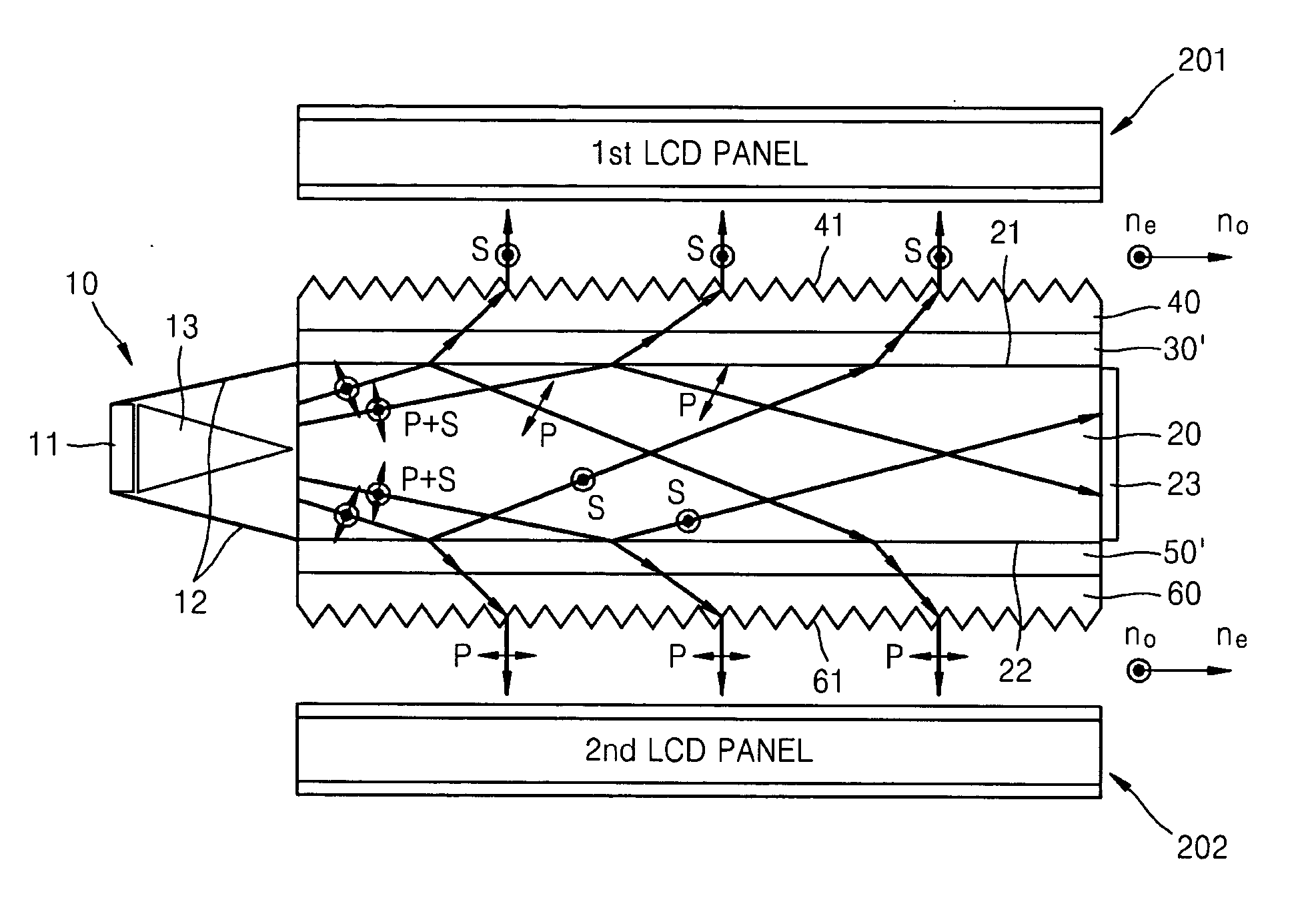
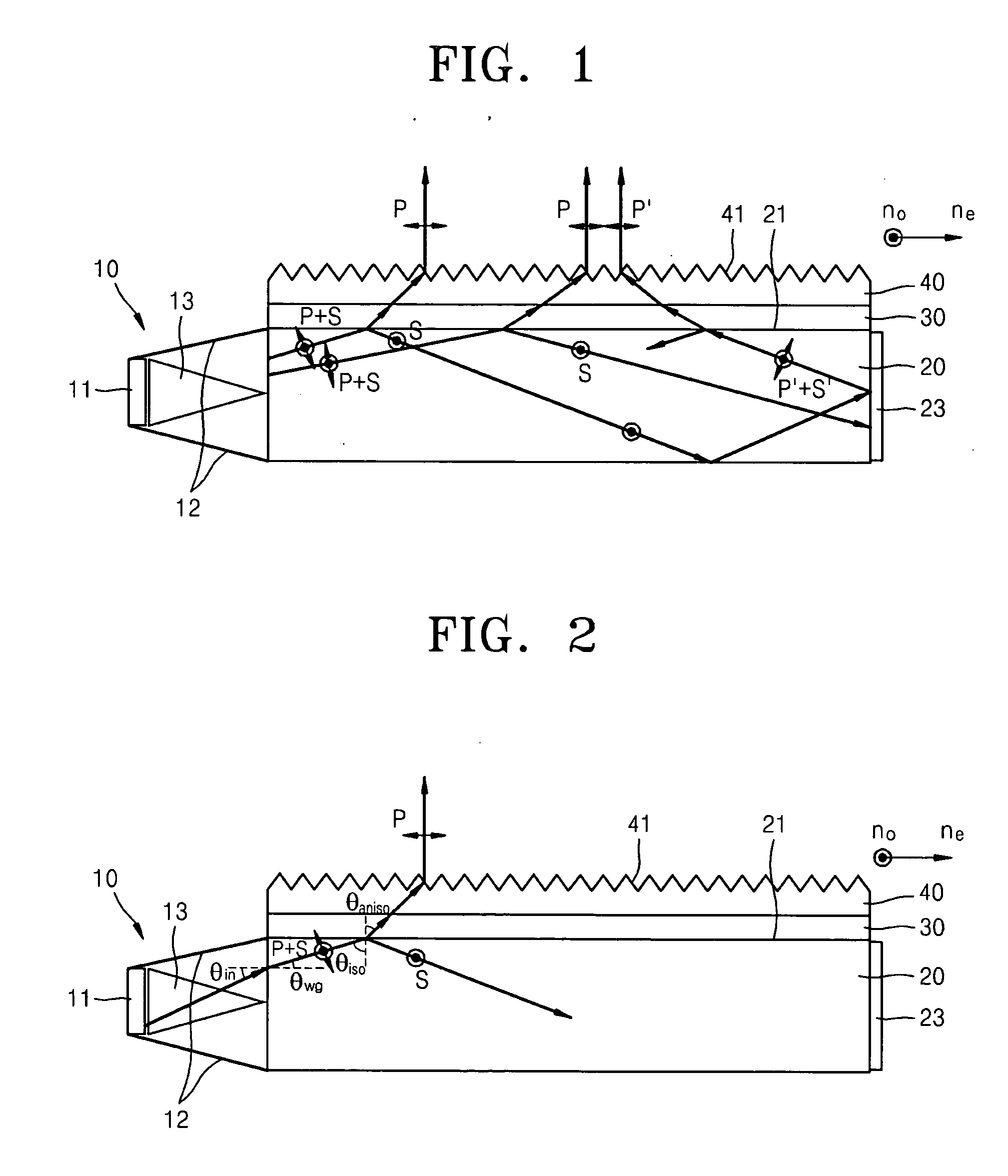
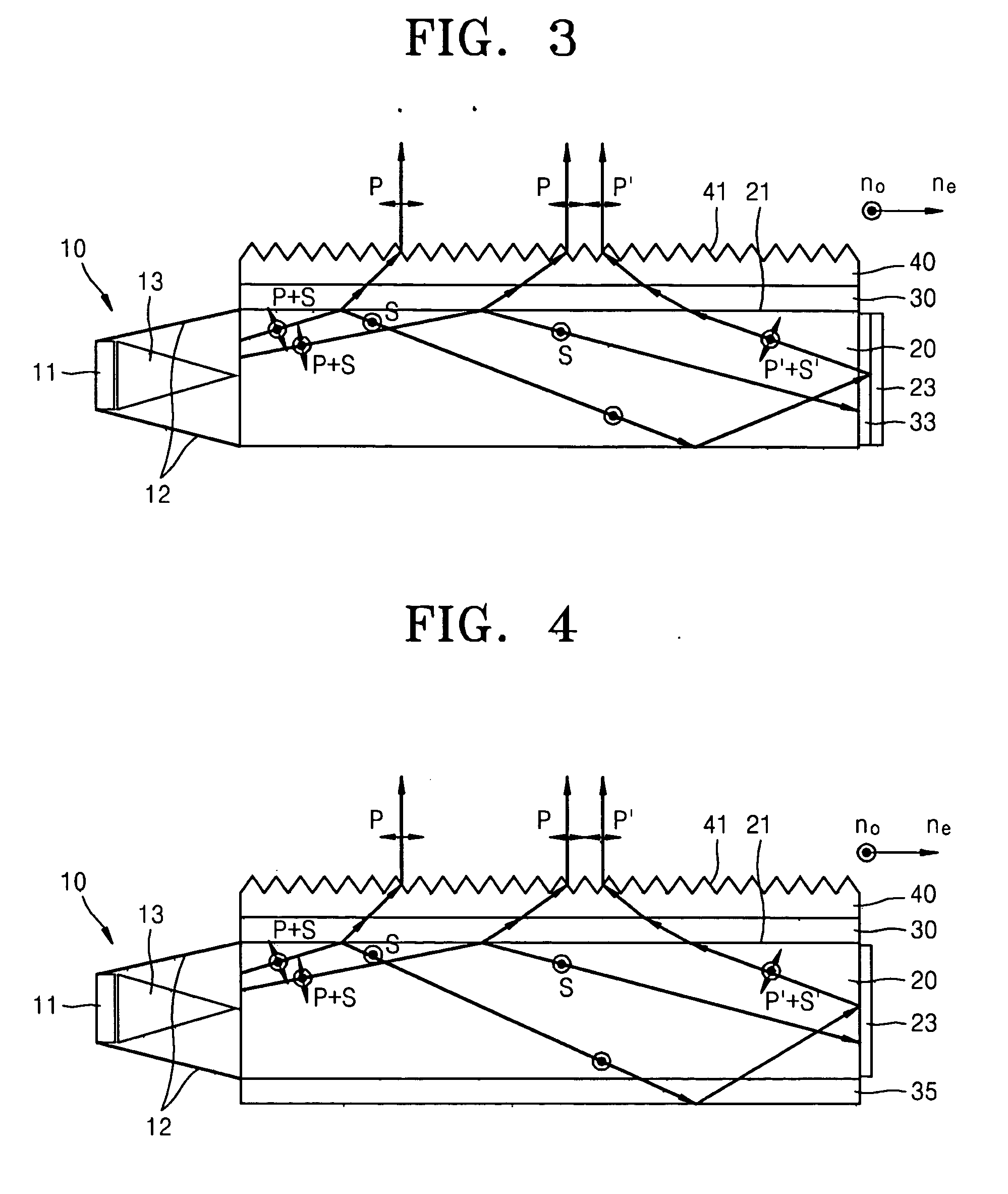
[0013] The present invention provides an illuminator for a flat panel display device having a light guide structure which out-couples first polarized light and recycles second polarized light by changing the polarization of the second polarized light or depolarizing and separating the second polarized light again, thus maximizing light efficiency.
[0014] The present invention also provides a light out-coupling structure which minimizes light loss and is manufactured easily, and a collimator which can collimate light sufficiently within a short region.
[0015] According to an aspect of the present invention, there is provided an illuminator for a flat panel display in which polarized light is separated in a light guide structure to out-couple first and second polarized light through opposite sides to improve light efficiency.
[0021] The beam out-coupling layer may be formed of optically isotropic material. If the beam out-coupling layer is optically anisotropic, it is difficult to form a fine solid pattern on a surface of the beam out-coupling layer. Thus, if the beam out-coupling layer is formed of optically isotropic film, efforts and costs for manufacturing of a beam out-coupling layer can be reduced.
[0024] The illuminator for a double-sided flat panel display device uses a light guide plate and the first and second polarization separation layers formed on both sides of the light guide plate to separate perpendicular polarized elements so that the perpendicular polarized elements separated from a light source can be used on both sides of the light guide plate. Thus, loss of optical energy due to absorptive polarizer is eliminated and loss due to scattering which occurs inevitably during reflection or transmission can be minimized.

Problems solved by technology

However, since the light emitted from the backlight unit through the light guide plate is unpolarized, it cannot be used as is in a liquid crystal display and needs to be polarized through a linear polarizer.
Through a linear polarizer, half of the optical energy is lost, thereby reducing energy efficiency, and the lost light is converted into heat and causes a heat generation problem.
However, since the difference in the refractive indices is not sufficient, a collimator for guiding the light toward the light guide structure at an angle sufficient for total internal reflection is required as mentioned in U.S. Pat. No. 5,808,709.
If collimation is not sufficient, separation is not properly achieved.
However, a conventional collimator requires a relatively long distance from a light source.
However, it is difficult to form the fine solid structure on the surface of the optically anisotropic layer and the processing of the fine solid structure is not efficient.
A material used to secure a sufficient thickness for an optically anisotropic light guide plate is also limited.
However, the illuminator in 2005-070201 includes an unpolarized light guide plate made of a double-sided prism which requires an absorption polarizer on both sides and thus has low energy efficiency.
Because the reflected polarized light passes the light guide plate again, partial light loss or the depolarization of the wanted polarization may easily occur.

Method used


Image

  • Illuminator for flat panel display device and illuminator for double-sided flat panel display device
  • Illuminator for flat panel display device and illuminator for double-sided flat panel display device
  • Illuminator for flat panel display device and illuminator for double-sided flat panel display device

Examples


Embodiment Construction

[0046] The present invention will now be described more fully with reference to the accompanying drawings, in which exemplary embodiments of the invention are shown. Like reference numerals denote like elements throughout the drawings, and descriptions for the like reference numerals will not be repeated.

[0047]FIG. 1 is a cross-sectional view of an illuminator for a flat panel display device according to an exemplary embodiment of the present invention. The illuminator of FIG. 1 includes a light source 11, a collimator 10 collimating the light generated by the light source 11, and a light guide structure in which the incident light from the collimator 10 is uniformly distributed onto the entire flat panel display device. In the light guide structure, the incident light is polarized and separated so that first polarized light P is out-coupled, and then second polarized light S is recycled and its polarization is converted into first polarized light P, and then the first polarized li...


PUM


Abstract

An illuminator for a flat panel display device is provided. The illuminator includes a light source generating light; a light guide plate that guides and distributes the light generated by the light source and is made of optically isotropic material; a collimator that is disposed between an end of the light guide plate and the light source and guides the light from the light source onto the light guide plate with a predetermined incident angle; a polarization separation layer that is made of optically anisotropic material having two refractive indices and formed on the light guide plate to transmit first polarized light from the light guide plate and reflect second polarized light from the light guide plate; and a beam out-coupling layer that is formed on the polarization separation layer and out-couples the light incident from the polarization separation layer.

Description

CROSS-REFERENCE TO RELATED PATENT APPLICATION [0001] This application claims priority from Korean Patent Application Nos. 10-2005-0081845 and 10-2006-0049298, filed on Sep. 2, 2005 and Jun. 1, 2006, respectively, in the Korean Intellectual Property Office, the disclosures of which are incorporated herein in their entirety by reference. BACKGROUND OF THE INVENTION [0002] 1. Field of the Invention [0003] The present invention relates to an illuminator for a flat panel display device, and more in particular, to an illuminator in which incident light from a light source placed on one side of a light guide plate is separated into different polarized light and out-coupled to the flat panel display device. [0004] 2. Description of the Related Art [0005] Flat panel displays are classified into light emitting display devices and light receiving display devices. A liquid crystal display device is a light receiving display device which does not form an image by emitting light by itself, but by...

Claims


Application Information

Patent Timeline
IPC IPC(8): G02F1/1335
CPCG02B6/0053G02F1/13362G02B6/0056
Inventor HWANG, SEONG-MOLEE, MOON-GYUKIM, YOUNG-CHANWEE, DONG-HONAM, SEUNG-HOKIM, KYUNG-YEUP
Owner SAMSUNG ELECTRONICS CO LTD
Learn More