Eureka AIR delivers breakthrough ideas for toughest innovation challenges, trusted by R&D personnel around the world.

Screening method and apparatus

Active Publication Date: 2007-03-08
KOPP DEV
View PDF0 Cites 31 Cited by
  • Summary
  • Abstract
  • Description
  • Claims
  • Application Information

AI Technical Summary

Benefits of technology

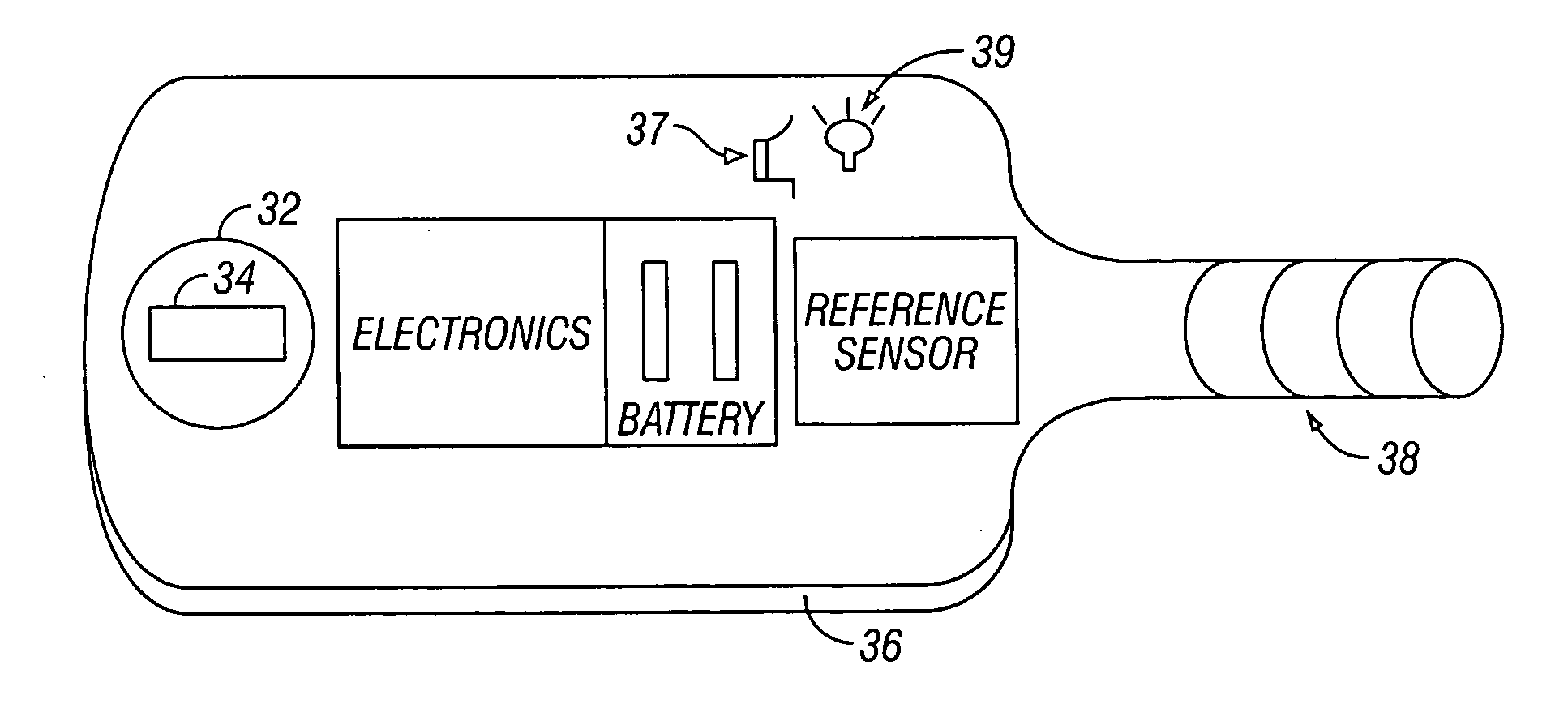
[0025] The present invention can be configured as a DC sensing system, or as an AC sensing system. Both sense magnetic fields, but in different ways. A detection head configuration, consisting of a magnetization source, the sensor elements, and possibly part, or all, of the associated electronics, is positioned as closely as possible to the detection region of interest. The detection head configuration can have a non-ferromagnetic casing. Positioning the detection head configuration as close to the ferromagnetic threat object as possible is very important, as this greatly increases detectability.
[0027] Adding body movement, when feasible, such as having the patient actively tilt and / or rotate his or her head, or, alternatively, having the technician perform these movements on the patient, increases the likelihood of ferromagnetic detection and diminishes the possibility of a false negative.
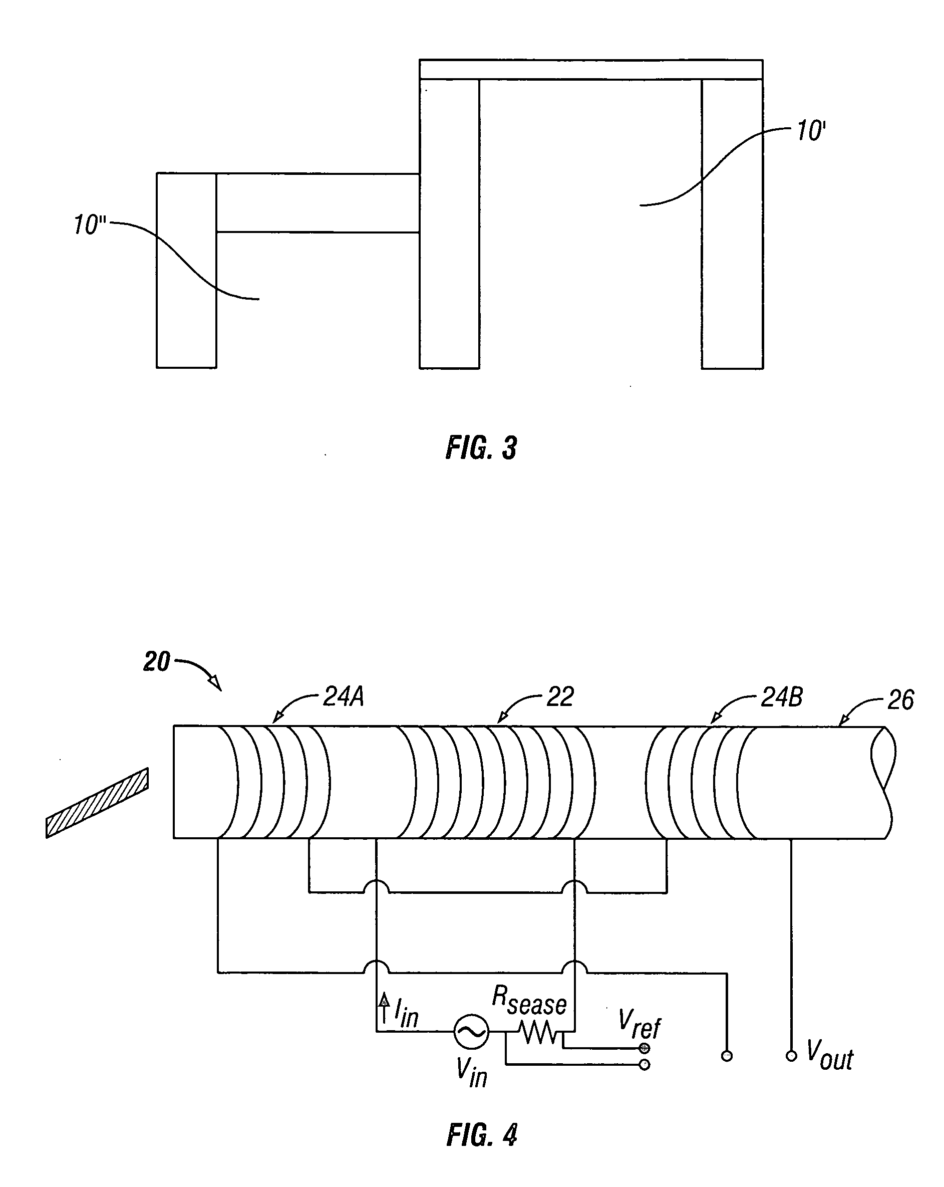
[0032] The sensors are preferably configured in gradiometer format to minimize, or eliminate, unwanted signals from distant moving ferromagnetic sources, such as elevators, chairs, or cars moving in a parking garage or a near-by street. An alarm, preferably with both audio and visual components, is activated whenever a ferromagnetic threat object is detected. If desired, an interlock can be provided, preventing access into the MRI magnet room or energization of the MRI magnet.

Problems solved by technology

Although motorized control can be used to direct the screening movements of the detection head configuration, hand direction and manipulation of the detection head configuration is usually preferred, because the use of motors to direct movement can introduce noise, thereby degrading the signal being sensed.

Method used


Image

  • Screening method and apparatus
  • Screening method and apparatus
  • Screening method and apparatus

Examples


Embodiment Construction

[0045] The present invention, which applies to both permanently magnetic objects and non-permanent magnetically susceptible objects, can use magnetometers with good sensitivity at frequencies all the way, or nearly, to DC, i.e., zero frequency. This allows several modes of use:

[0046] (1) A completely passive system detects ferromagnetic objects using their permanent magnetization, or the magnetization induced by the Earth's magnetic field.

[0047] (2) A system can apply a DC magnetic field, allowing control and usually enhancement of the magnetization of objects, thus enhancing their detectability.

[0048] (3) An AC magnetic susceptometer applies an oscillating AC magnetic field, but at very low frequencies compared to conventional detectors, allowing enhancement of their magnetization. The purpose of AC illumination is to move the signal from DC to a region of lower noise at finite frequency. The AC frequency is chosen to avoid inducing the electrical eddy currents detected by other...


PUM


Abstract

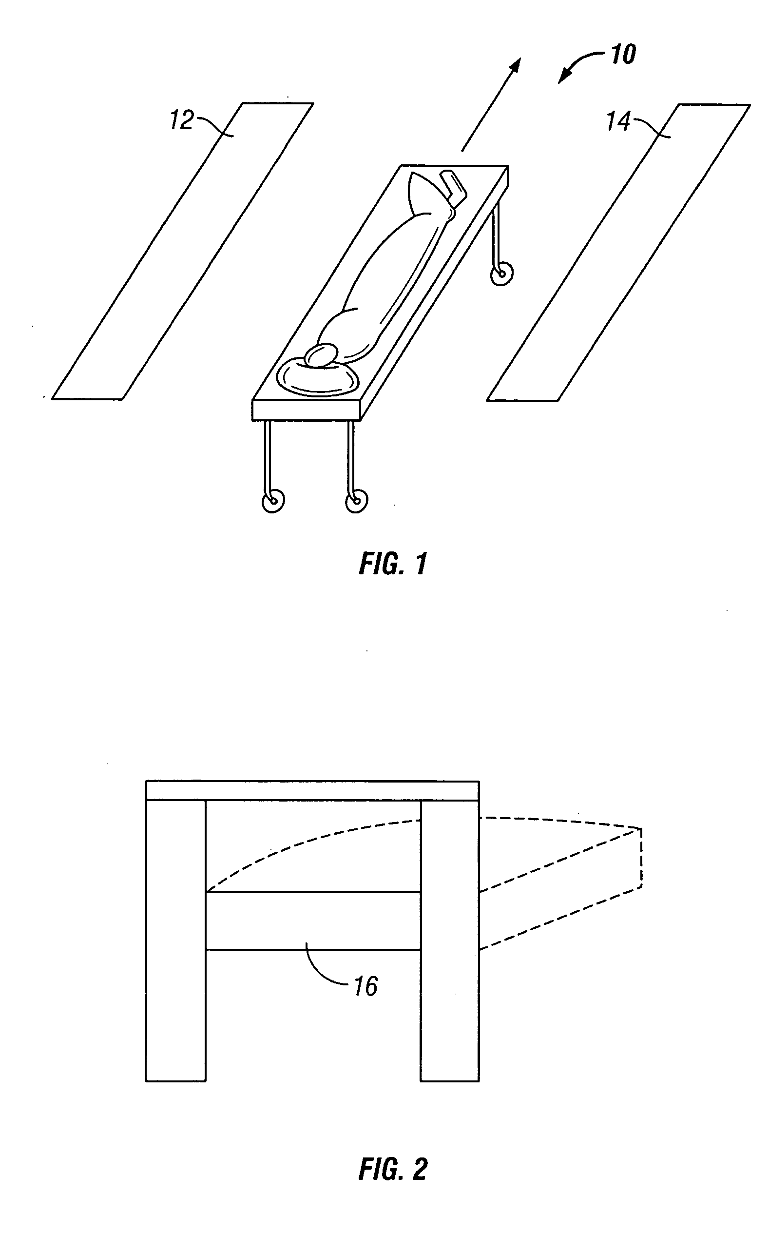
A method and an apparatus are disclosed, to screen patients or other areas for ferromagnetic objects, particularly for use intra-operatively in an operating room. The device comprises at least one magnetic field source, at least one magnetic gradiometer, and the associated electronics. The field source and the gradiometer are supported by an arm structure which can be manipulated to position the field source and the gradiometer at one or more positions near areas of interest, such as areas on a patient or other subject, and to orient the field source and the gradiometer so that the axis of the magnetic field is arranged along three different non-parallel, non-coplanar, axes to ensure detection of any ferromagnetic object regardless of its shape and orientation. The device can be manipulated to place the sensor arrays in close proximity to selected parts of a subject's body, for screening purposes. Two field sources and two gradiometers can be provided, for positioning on two sides of a portion of the subject's body, such as the head.

Description

CROSS REFERENCE TO RELATED APPLICATIONS [0001] This is a continuation-in-part application of co-pending U.S. application Ser. No. 10 / 703,147, filed Nov. 05, 2003, for “Security Screening Method and Apparatus”, which is a continuation application of co-pending U.S. application Ser. No. 10 / 681,033, filed Oct. 07, 2003, for “Magnetic Resonance Imaging Screening Method and Apparatus”. This is also a continuation-in-part application of co-pending U.S. Application Ser. No. 10 / 681,033, filed Oct. 27, 2003, for “Magnetic Resonance Imaging Screening Method and Apparatus”. The parent applications also rely upon U.S. Provisional Pat. App. No. 60 / 440,697, filed Jan. 17, 2003, for “Method and Apparatus to Use Magnetic Entryway Detectors for Pre-MRI Screening”, and U.S. Provisional Pat. App. No. 60 / 489,250, filed Jul. 22, 2003, for “Ferromagnetic Wand Method and Apparatus for Magnetic Resonance Imaging Screening”.STATEMENT REGARDING FEDERALLY SPONSORED RESEARCH OR DEVELOPMENT [0002] Not Applicabl...

Claims


Application Information

Patent Timeline
IPC IPC(8): G01R33/12A61B5/06G01V3/08G01V3/15
CPCA61B5/06G01V3/15G01V3/08
Inventor MCCLURE, RICHARD J.JEFFERS, FREDERICK J.MASSENGILL, R. KEMP
Owner KOPP DEV
Why Eureka
Eureka Blog
Learn More