
Storage system and storage system management method

a storage system and management method technology, applied in error detection/correction, redundancy hardware error correction, instruments, etc., can solve the problems of increased structural complexity, data processing services cannot be provided to hosts, and the load of one secondary storage control device is increased, so as to reduce the storage capacity to store correspondence relations, reduce the amount of storage, and reduce the switching time

Active Publication Date: 2007-03-01
HITACHI LTD
View PDF3 Cites 34 Cited by
  • Summary
  • Abstract
  • Description
  • Claims
  • Application Information

AI Technical Summary

Benefits of technology

The present invention provides a storage system and management method that can secure redundancy even when one of the control devices fails. The system includes multiple storage control devices, each responsible for managing data in a different data volume. The first control device sets the control number for data and sends it to the second control device, which in turn stores it in a journal volume. The second control device reads the journal volume and stores the data in the second data volume. The third control device reads the journal volume and updates the stored data. This ensures that the data is synchronized and reduces the possibility of differences between the three data volumes. The system also allows for switching between the control devices and provides a differential management table to manage the differences between data volumes. The technical effects of this invention include securing redundancy, simplifying the management of a storage system, and improving the convenience of use.

Problems solved by technology

However, if a malfunction occurs in the sole backup site, data processing services cannot be provided to hosts.
However, in the first reference, the one secondary storage control device must generate journal data each time data updating is performed, so that the load on the one secondary storage control device is increased.
Moreover, a volume must be provided to save the journal data in the one secondary storage control device, so that there is the problem of increased structural complexity.

Method used


Image

  • Storage system and storage system management method
  • Storage system and storage system management method
  • Storage system and storage system management method

Examples


embodiment 1

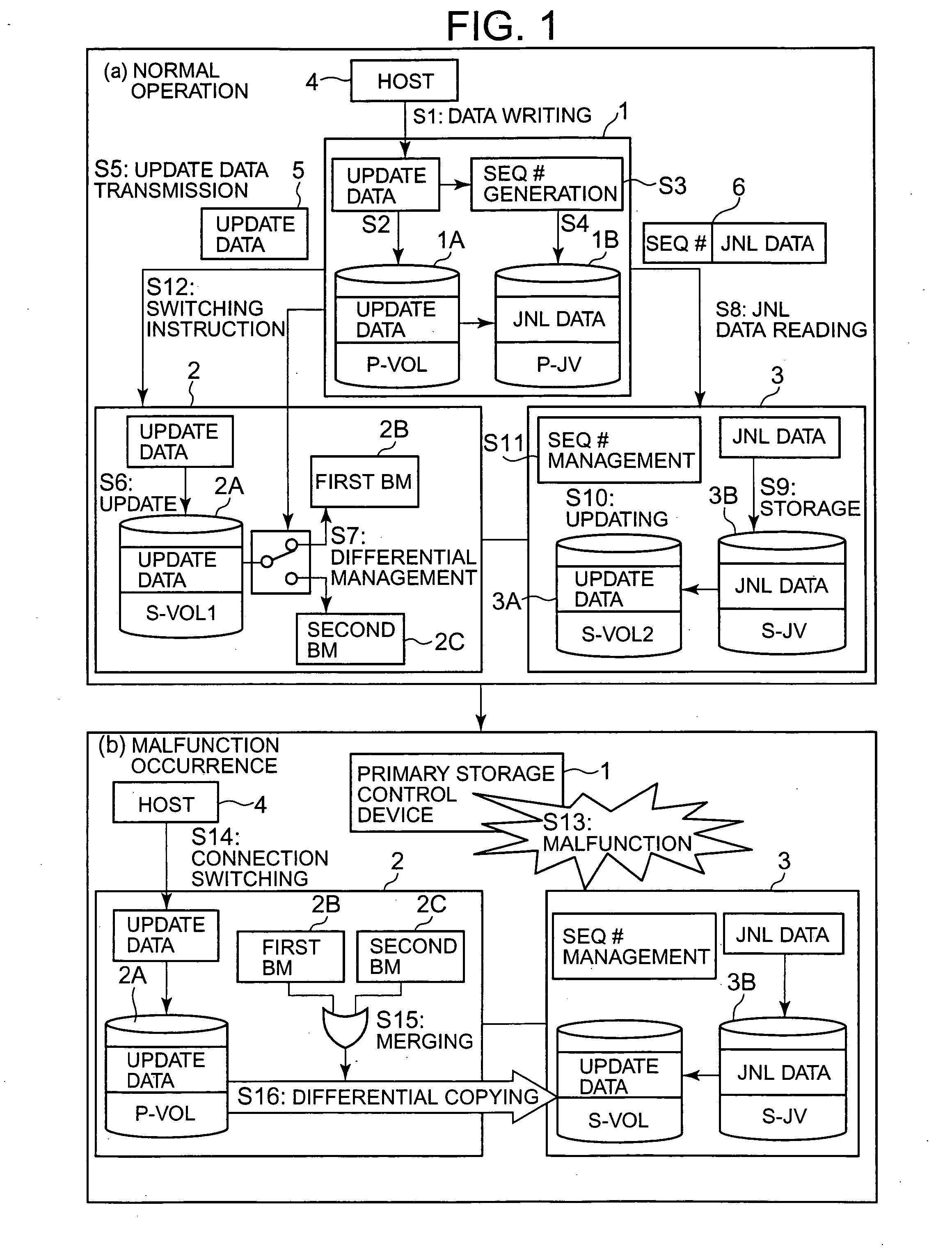
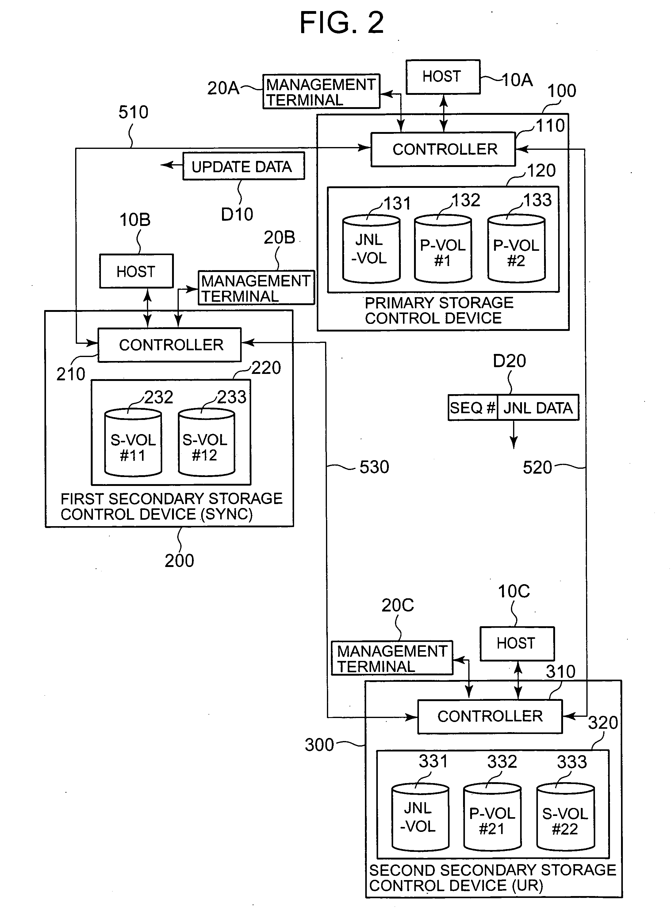
[0069]FIG. 2 shows the overall configuration of a storage system of this invention. The correspondence relations with FIG. 1 are as follows. The primary storage control device 100 corresponds to the primary storage control device 1 in FIG. 1; the first secondary storage control device 200 corresponds to the first secondary storage control device 2 in FIG. 1; the second secondary storage control device 300 corresponds to the second secondary storage control device 3 in FIG. 1; and the host 10A corresponds to the host 4 in FIG. 1.

[0070] This storage system can be configured comprising one or more primary storage control devices 100, a plurality of secondary storage control devices 200, 300, hosts 10A, 10B, 10C, and management terminals 20A, 20B, 20C. At least a portion of the hosts 10A, 10B, 10C and management terminals 20A, 20B, 20C may be the same. For example, the hosts 10A and 10B, and the management terminals 20A and 20B, may respectively be the same devices.

[0071] During norma...

embodiment 2

[0172] A second embodiment of the invention is explained, referring to FIG. 20. The following embodiments, including this embodiment, are equivalent to modified examples of the first embodiment. In this embodiment, four storage control devices are used to enhance the redundancy of the storage system.

[0173] In FIG. 20, (a) shows the state during normal operation. In this storage system, in addition to the primary storage control device 100, first secondary storage control device 200, and second secondary storage control device 300, a third secondary storage control device 400 is provided.

[0174] As explained in the first embodiment, the primary storage control device 100 and first secondary storage control device 200 are connected by a synchronous method, and the primary storage control device 100 and second secondary storage control device 300 are connected by an asynchronous reading method.

[0175] (b) in FIG. 20 shows a case in which a malfunction or similar has occurred in the pr...

embodiment 3

[0178] A third embodiment is explained using FIG. 21. In this embodiment, the correspondence relations between the storage control devices 100, 200, 300 are not held by the storage control devices 100, 200, 300, but the secondary storage control devices 200 and 300 each hold only the correspondence relation with the primary storage control device 100.

[0179]FIG. 21 is a flowchart showing a portion of the processing executed by the storage system of the third embodiment. This flowchart corresponds to the flowchart of FIG. 18, and includes common steps. Here explanations of the common steps are omitted, and the characteristic steps are mainly explained.

[0180] After S79, the host 10B issues a request for transmission of pair confirmation information to the second secondary storage control device 300 (S101). Pair confirmation information is information used to confirm the correspondence relation between the first secondary data volumes 232, 233 and the second secondary data volumes 332...


PUM


Abstract

A storage system secures system redundancy through a simple configuration. A primary storage control device and first secondary storage control device are connected by a synchronous method, and the primary storage control device and a second secondary storage control device are connected by an asynchronous method. The primary storage control device sets control numbers for update data, and saves journal data. The primary storage control device transmits the update data to the first secondary storage control device. The first secondary storage control device writes update data to a first secondary volume, and uses a plurality of bitmap tables to manage differences. If the primary storage control device stops operation, the first secondary storage control device becomes the new primary storage control device. Differential copying is performed from the first secondary storage control device to the second secondary storage control device.

Description

CROSS-REFERENCE TO RELATED APPLICATIONS [0001] This application relates to and claims priority from Japanese Patent Application No. 2005-253440, filed on Sep. 1, 2005, the entire disclosure of which is incorporated herein by reference. BACKGROUND OF THE INVENTION [0002] 1. Field of the Invention [0003] The present invention relates to a storage system and a management method for a storage system. [0004] 2. Description of the Related Art [0005] A storage system comprises at least one storage control device, called for example a disk array subsystem or similar, and provides data storage services to host computers (hereafter “hosts”). A storage control device can construct a storage area based on a RAID (Redundant Array of Independent Disks) system, in which numerous disk drives are arranged in an array. [0006] As is known in so-called disaster recovery systems, it is possible to position a backup site remotely from the primary site in anticipation of widespread disasters and similar. ...

Claims


Application Information

Patent Timeline
Patent Type & Authority Applications(United States)
IPC IPC(8): G06F12/16
CPCG06F11/2058G06F11/2069G06F2201/855G06F11/2076G06F11/2074
Inventor KAIYA, KEIICHIOKUMOTO, KATSUHIROKONDOU, SHUJI
Owner HITACHI LTD
Learn More