
Driving method of stacked light modulating device, and driving device of stacked light modulating device

a technology of stacked light and driving device, which is applied in the direction of static indicating device, optics, instruments, etc., can solve the problems of difficult enhancement of operation margin and difficulty in obtaining sufficient brightness, and achieve stable threshold value shifting operation and enhance operation margin

Inactive Publication Date: 2007-03-01
FUJIFILM BUSINESS INNOVATION CORP
View PDF7 Cites 9 Cited by
  • Summary
  • Abstract
  • Description
  • Claims
  • Application Information

AI Technical Summary

Benefits of technology

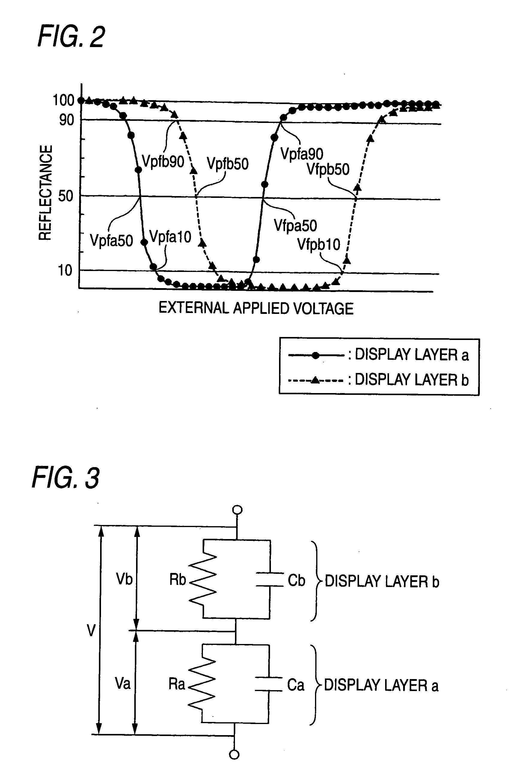
[0048] In other words, the voltage is divided by utilizing the resistance ratio between the display layers to eliminate necessity of a large dielectric constant ratio between the liquid crystal materials of the display layers, where by a liquid crystal material having a large refractive index anisotropy Δn can be used in the display layers to obtain a bright displayed image. Furthermore, the threshold electric fields of the display layers can be prevented from being reversed to each other by suppressing the dielectric constant ratio, whereby the operation margin can be easily enhanced. The pulse waveform applied may be a square wave, but an upward triangular wave, a sine wave and direct current pulses providing larger influence of the resistance component are preferably used.
[0052] It is understood therefore that, with respect to the operation margin for the lower threshold values, the relaxation time constant from the capacitance partial voltage ratio to the resistance partial voltage ratio of the voltages applied to the display layers is lowered, and pluses having a frequency and waveform providing large influence of the resistance component are applied to utilize the resistance ratio of the layers, whereby the restriction in dielectric constant is reduced to increase significantly the degree of freedom on designing the liquid crystal materials.
[0054] As having been described, there is such a tendency that the operation margin at the upper threshold value easily becomes larger than the operation margin at the lower threshold value, and thus the device can be operated with the capacitance partial voltage even when the dielectric constant ratio is relatively small. In the invention, the writing operation at the upper threshold value is differentiated in frequency of the applied voltage from the writing operation at the lower threshold value, so as to solve the problems. In the aforementioned embodiment, the frequency of the applied voltage is made small for securing the operation margin at the lower threshold value to attain relaxation to the resistance partial voltage ratio, and on the other hand, the frequency is increased in the switching operation at the upper threshold value, which is liable to receive influence of turbulence in waveform caused by a voltage of a s low frequency, whereby the operation margin is secured with maintaining stable operation.
[0055] The frequencies of the applied voltages may be reversed each other depending on various properties of the stacked light modulating device used. The substantial feature of the invention is that the frequencies of the applied voltages, which have been the same as each other with no idea of differentiating from each other, are differentiated between the writing (switching) operation at the upper threshold value and that at the lower threshold value, which realizes sufficient operation margins and stable operation, and enhances the degrees of freedom in drive design, equipment design and device design of the stacked light modulating device, such as the material design of the device.
[0056] In a preferred embodiment, a conventional wavelength utilizing the capacitance partial voltage, i.e., a voltage with a high frequency, is applied at the upper threshold value, and a wavelength utilizing the resistance partial voltage, i.e., a voltage with a low frequency, is applied at the lower threshold value. According to the operation, voltages with different frequencies (or different waveforms) are applied as a voltage applied at the upper threshold value (reset voltage) and a voltage applied at the lower threshold value (select voltage), respectively, whereby the stacked light modulating device can be operated with a display layer having a high reflectance realized, and therefore the practicality of the stacked light modulating device using the threshold value shifting method is significantly improved.
[0058] According to the invention, such a driving method and a driving device of a stacked light modulating device utilizing the threshold value shifting method can be provided that enhance the operation margin while maintaining sufficient reflectance in display layers of the stacked light modulating device, so as to realize stable threshold value shifting operation.

Problems solved by technology

However, a cholesteric liquid crystal generally has relationships between the relative dielectric constant and the refractive index anisotropy Δn and between the refractive index anisotropy Δn and the reflectance, and therefore, in the case where the ratio in dielectric resistance between the display layers is increased, it is difficult to obtain sufficient brightness with the display layer having a lower dielectric constant.
Furthermore, a cholesteric liquid crystal having such a tendency that the threshold electric field is decreased with increase of the specific dielectric constant, and therefore, the voltages applied to the display layers and the threshold electric fields of the display layers may be reversed to each other, which makes enhancement of the operation margin difficult.

Method used


Image

  • Driving method of stacked light modulating device, and driving device of stacked light modulating device
  • Driving method of stacked light modulating device, and driving device of stacked light modulating device
  • Driving method of stacked light modulating device, and driving device of stacked light modulating device

Examples


first embodiment

[0077]FIG. 1 is a schematic constitutional view showing a first embodiment as one exemplary embodiment of a system, to which the driving method of a stacked light modulating device of the invention. The system according to the embodiment contains a display medium (stacked light modulating device) 1 and a writing device (a driving device of a stacked light modulating device) 2. Both the constitutional elements will be firstly described, and then the operation thereof will be described.

(Display Medium)

[0078] The display medium in the embodiment is such a member that can be selectively driven with plural liquid crystal layer (selective reflection layers) by applying a bias signal, and is specifically a stacked light modulating device.

[0079] The display medium 1 of the embodiment has, stacked from a display surface in this order, a transparent substrate 3, a transparent electrode 5, a display layer (selective reflection layer) 7b, a display layer (selective reflection layer) 7a, a t...

second embodiment

[0123]FIG. 12 is a schematic constitutional view showing a second embodiment as one exemplary embodiment of a system, to which the driving method of a stacked light modulating device of the invention. As similar to the first embodiment, the system according to the second embodiment contains a display medium (stacked light modulating device) 1′ and a writing device (a driving device of a stacked light modulating device) 2′, provided that the second embodiment is different from the first embodiment in such a point that the display medium (stacked light modulating device) 1′ contains a photoconductor layer, and the writing device (a driving device of a stacked light modulating device) 2′ also has a different constitution corresponding thereto.

[0124] In the following description, the differences of the second embodiment in constitution, function and advantage from the first embodiment are described, and the members having the same functions as in the first embodiment are attached with ...


PUM

PropertyMeasurementUnit
frequency FV2aaaaaaaaaa
reflectanceaaaaaaaaaa

Abstract

A driving method of a stacked light modulating device for recording an image therein, which includes selective reflection layers each having a cholesteric liquid crystal, reflecting light with different wavelengths within a visible range, and being different in a lower threshold value of texture change from a planar to a focal conic texture with respect to an externally applied voltage and an upper threshold value of texture change from the focal conic to a homeotropic texture, and a pair of electrodes disposed outside, includes applying between the pair of electrodes voltages including a voltage V1 and have a same frequency, to select an area exceeding or not exceeding the upper threshold value in each of the selective reflection layers, and applying voltages including a voltage V2 and have a same frequency different from the voltage V1, to select an area exceeding or not exceeding the lower threshold value.

Description

BACKGROUND OF THE INVENTION [0001] 1. Field of the Invention [0002] The present invention relates to a driving method and a driving device for writing an image in a stacked light modulating device, which contains plural selective reflection layer containing a liquid crystal and displays and records an image of two or more colors. [0003] 2. Description of the Related Art [0004] There is increasing expectation of a rewritable marking technique as an alternative to paper as a hardcopy technique due to such reasons as protection of the global environment including forest resources and space saving. [0005] A reflective liquid crystal display device is receiving attention as a display device for a compact information processing equipment and a personal digital assistant since it requires no dedicated light source like aback light, consumes a small amount of electric power, and can be constituted to a thin and small size. [0006] Various techniques using a reflective liquid crystal display ...

Claims


Application Information

Patent Timeline
Patent Type & Authority Applications(United States)
IPC IPC(8): G09G3/36
CPCG02F1/13476G02F1/135G02F2001/13775G02F2001/13478G02F1/13718G02F1/13478G02F1/13775
Inventor GAN, TAIJYUHARADA, HARUOOKANO, YASUNORIGOMYOU, MAKOTOARISAWA, HIROSHI
Owner FUJIFILM BUSINESS INNOVATION CORP
Learn More