
Bin level indicator

Inactive Publication Date: 2007-02-22
SMITH DANIEL R
View PDF8 Cites 10 Cited by
  • Summary
  • Abstract
  • Description
  • Claims
  • Application Information

AI Technical Summary

Benefits of technology

[0013] With specific regard to the present invention, I have provided a system for measuring the depth, and hence the quantity of material in a container, such as a bin. My novel component reliably detects the presence or absence of liquid or solid materials ranging from fine powder to large diameter prill. My instrument was designed primarily for use in the dry bulk material industry, with fertilizer being but one example. By monitoring the level of material in cluster bins, multi-celled holding hoppers, above the weigh hoppers, it not only saves the cost of labor but it also eliminates the health hazards associated with humans in close proximity to heavy concentrations of mineral dust.
[0022] Also important is that both installation and maintenance of my novel device requires no particular skill, but despite its non-complex configuration, it performs the task better, and at much lower cost, than any high tech equivalent.
[0023] It is thus a primary object of my invention to provide a sensor of uncomplicated, low cost construction, that can be effectively used for accurately determining the extent of fill in a bin.
[0024] It is another important object of my invention to provide a sensor or transducer of uncomplicated, low cost, non-clogging construction, that can be effectively used for accurately determining the extent of fill in a bin adapted to contain a wide range of different fill materials.
[0026] It is yet another object of my invention to provide a novel bin level indicator of simple construction, that does not need to be affixed to a wall of a bin for its operation, thus making it possible for my novel device to be used in multicell cluster hoppers, where ready access to the inner cells of the cluster is quite difficult.
[0029] It is still another object of my invention to provide a sensor having components adapted to be lowered into a bin containing material whose height or extent of fill is to be measured, which sensor utilizes a signal tube that can be recessed for a variable extent with respect to the lower tip of the exhaust tube, thus to make it possible to obtain the best signal pressure for each different material whose depth in the bin is to be measured.

Problems solved by technology

With regard to the minimization of dust, this is very important in the industry because close tolerance of the material is required by the United States Agricultural Department, and cross contamination, which occurs if one cell of a group overflows into the next, is not acceptable.
However, upon the degree of the fill of the bin or container being such that material begins to closely approach the remote end of the primary hose, the air normally flowing out of one of the hoses is caused to be deflected into the remote end of the other of the hoses, and thus causing the pressure in such other hose to increase.

Method used


Image

  • Bin level indicator
  • Bin level indicator
  • Bin level indicator

Examples


first embodiment

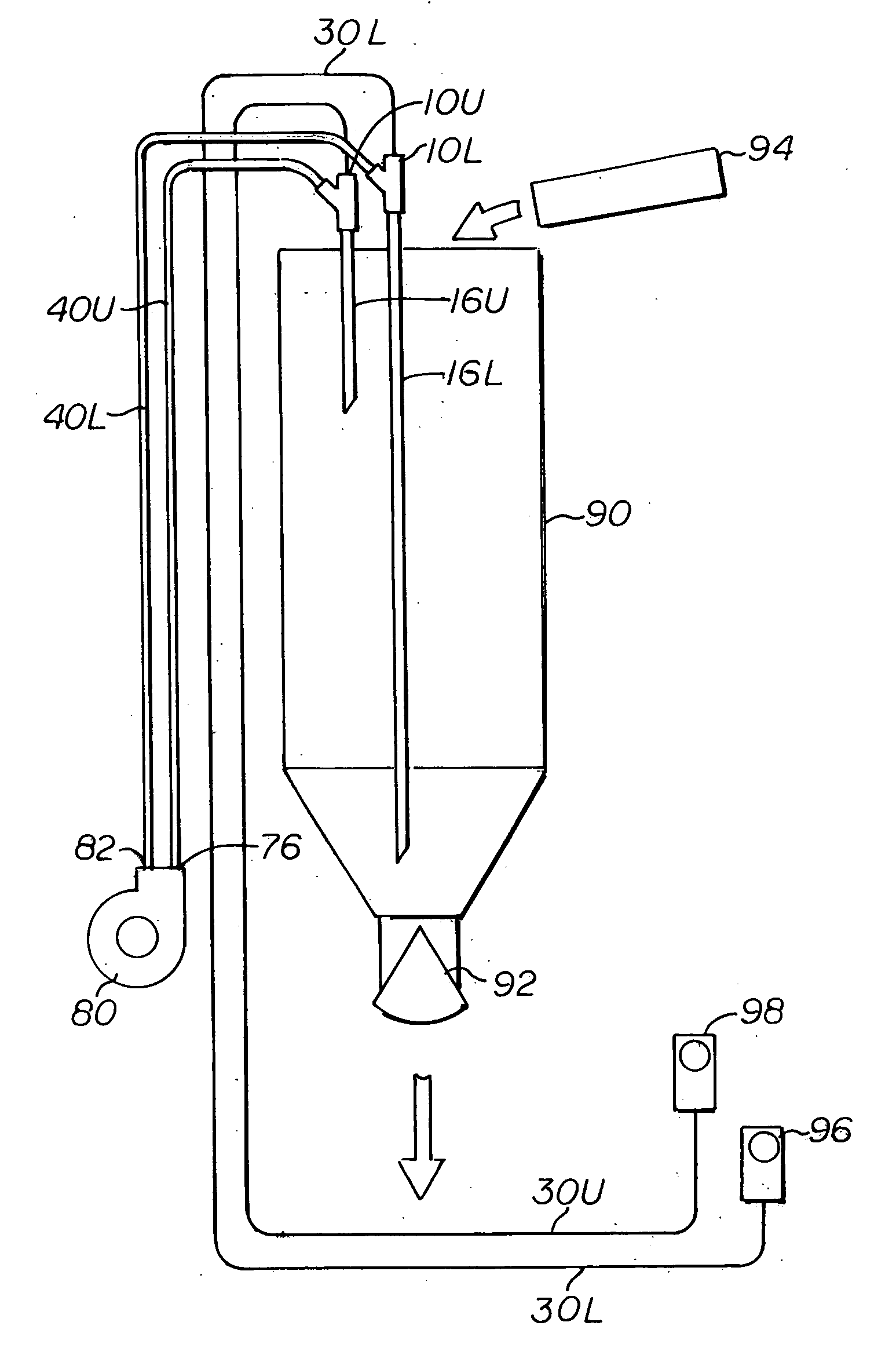
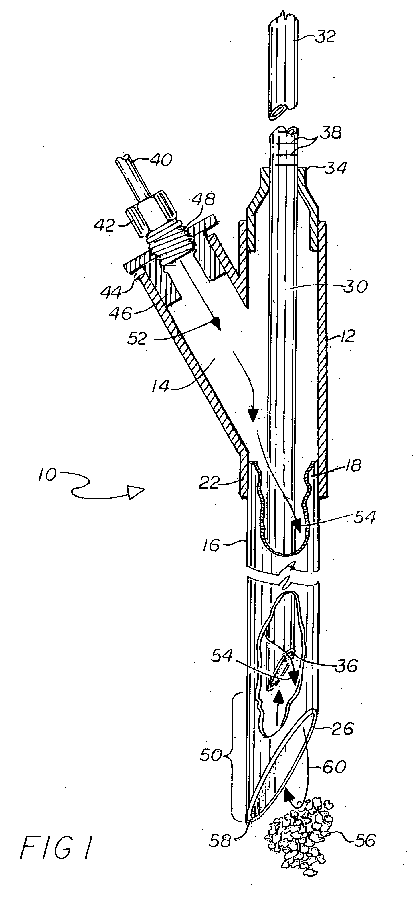
[0035] With initial reference to FIG. 1, my novel sensor 10 is illustrated, involving a housing or casing 12 in which a central chamber or bore 14 is defined. I may also refer to the device 10 as a transducer. The housing 12 may be of one-piece construction, and may be regarded as generally being in a “Y” shaped configuration and containing several apertures or orifices, to be described shortly. The housing 12 may be made of a suitable metal, or of an industrial grade plastic.

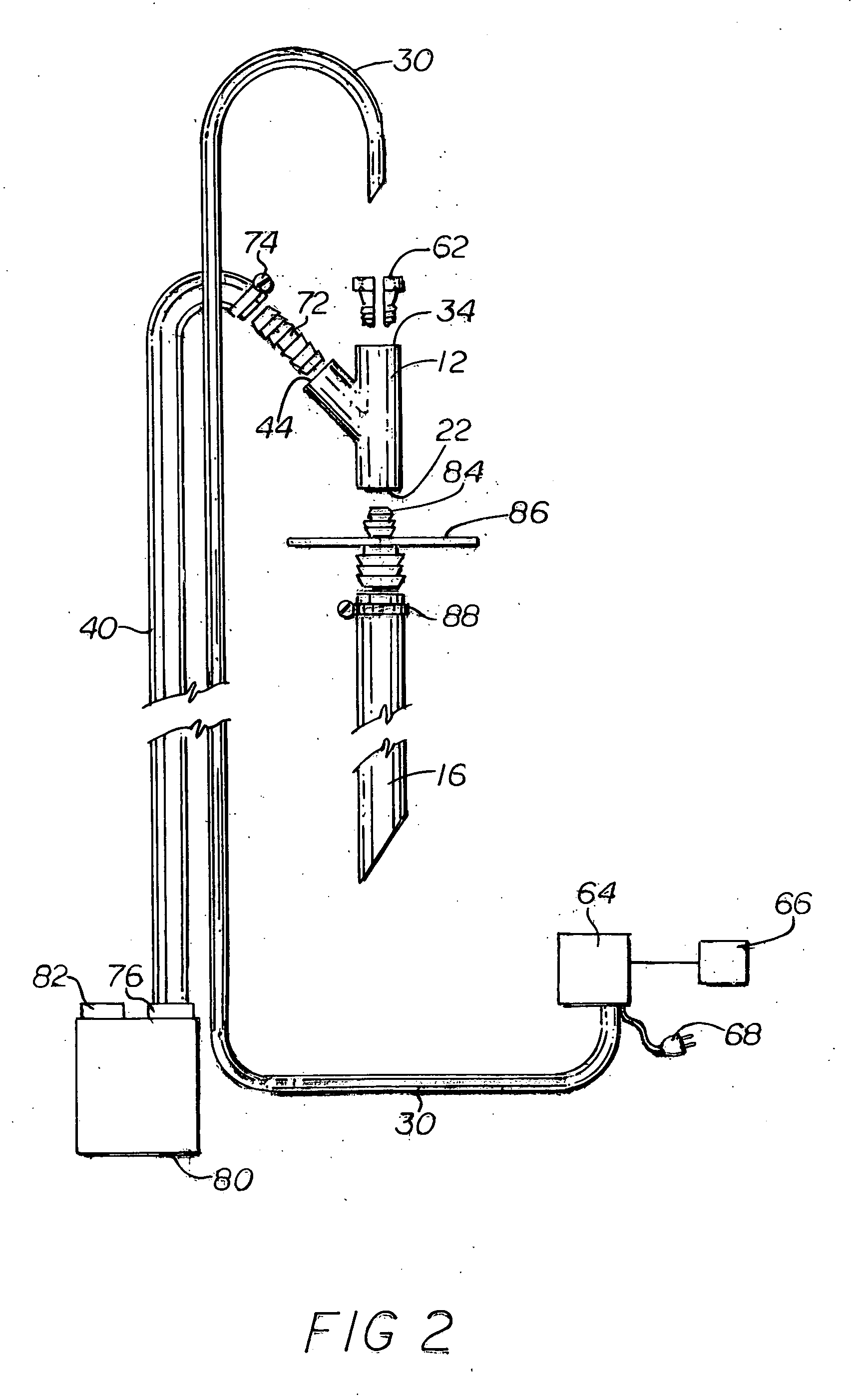
[0036] Inasmuch as my novel sensor 10 is typically utilized in a vertical attitude in a bin whose fill level is to be measured on a moment-by-moment basis, I have depicted the sensor 10 in a vertical attitude in FIG. 1. In FIG. 2 I have presented an exploded view of the housing 12 and its associated components, and in FIG. 3 I have illustrated a typical single bin installation, with which my invention may be used. In FIG. 4 I have depicted a typical multiple bin installation or multicell cluster hopper, as will...

second embodiment

[0052] It is to be noted that in accordance with another embodiment of my invention, the air flow arrangement may be reversed in order to enable a different type of material to be sensed. In accordance with this second embodiment, the previously-mentioned connector in the tube or hose 30 would be opened (broken), so as to be able to properly receive the pipe supplying compressed air at the first upper orifice 34. Continuing with this modification, the second upper orifice or aperture 44 in the offset portion of the housing 12 would be reconfigured to receive a proper connection to the remotely located pressure switch, or other readout device. I have found that when the level of an item such as pinto beans reside in the bin to be measured, it is advantageous for air to be admitted to the second upper orifice or aperture 44, as indicated in FIG. 1, whereas when the height of ground styrofoam residing in a bin is to be measured, it is more advantageous to supply the compressed air at t...


PUM


Abstract

A sensor involving a housing having a lower orifice to which a primary hose is connected. A secondary hose inside the primary hose is slightly shorter than the primary hose, with these hoses being placed inside a bin for determining fill level. One of two upper orifices in the housing is connected to a supply of air under pressure, with this air normally caused to flow outwardly from one of the hoses. Upon the degree of the fill of the bin being such that the material approaches the remote end of one of the hoses, the air normally flowing from the one hose is caused to be deflected into the remote end of the other of the hoses, causing a pressure increase. This pressure increase is directed through the other upper orifice, for being sensed at remotely located pressure sensing equipment.

Description

BACKGROUND OF THE INVENTION [0001] The present invention pertains to systems for measuring and indicating the depth of material in a container, such as a bin containing fertilizer. [0002] There are many instances in which it is desirable or necessary to provide a quick measurement of the amount of material stored in a container. In a typical industrial or agricultural setting, a bin or other container is provided for temporary storage of some material, such as fertilizer, grain, feed, cement, carbon black, etc. It is typical for quantities of material to be added to or withdrawn from the container from time to time, and the need arises for knowing the amount of material in the container at any given moment. [0003] It is not realistically possible to provide actual measurement of quantities of material added to and withdrawn from the container, in order to maintain a tally of its actual contents. Such schemes are generally not practical because of the length of time and degree of com...

Claims


Application Information

Patent Timeline
IPC IPC(8): G01F23/00
CPCG01F23/185
Inventor SMITH, DANIEL R.
Owner SMITH DANIEL R
Learn More