
Anchoring insert for embedding in a concrete component and concrete component provided therewith

a technology for anchoring inserts and components, applied in the direction of screws, structural elements, building components, etc., can solve problems such as complicated manufacturing, and achieve the effect of increasing separation resistan

Inactive Publication Date: 2007-02-22
ZAMBELLI SERGIO +1
View PDF21 Cites 43 Cited by
  • Summary
  • Abstract
  • Description
  • Claims
  • Application Information

AI Technical Summary

Benefits of technology

"The present invention provides an anchoring insert for prefabricated concrete components that has higher resistance to separation from the component than known types of anchoring inserts. The insert is simple and cost-effective to manufacture and can be used for a wide range of components, including low-thickness components. The insert has a reduced depth with respect to its resistance to separation, making it suitable for a wide range of applications. The insert body has at least one secondary opening that allows the concrete of the component to enter the compartment and protective means to prevent the concrete from accessing a portion of the compartment that is connected to the main opening and designed to receive the connecting element."

Problems solved by technology

One fundamental technical problem in the design of these inserts is to achieve the intended resistance of the insert to separation from the component in which it is embedded, with a minimal depth of the insert, where depth is the dimension of the insert at right angles to the face of the component that supports the insert and generally is the dimension of the insert along the thickness of the component.
All these refinements suffer the drawback of complicating the manufacture of the insert and often do not allow to combine a preset resistance to separation with the intended depth for the insert.

Method used


Image

  • Anchoring insert for embedding in a concrete component and concrete component provided therewith
  • Anchoring insert for embedding in a concrete component and concrete component provided therewith
  • Anchoring insert for embedding in a concrete component and concrete component provided therewith

Examples


Embodiment Construction

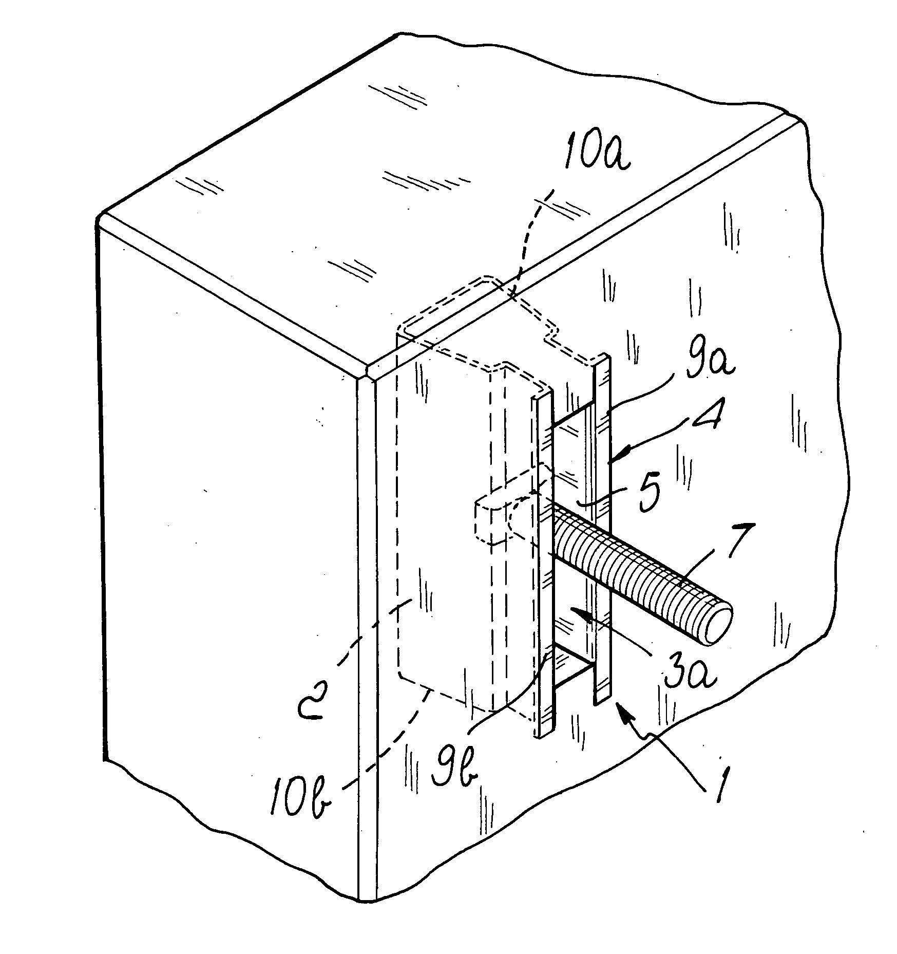
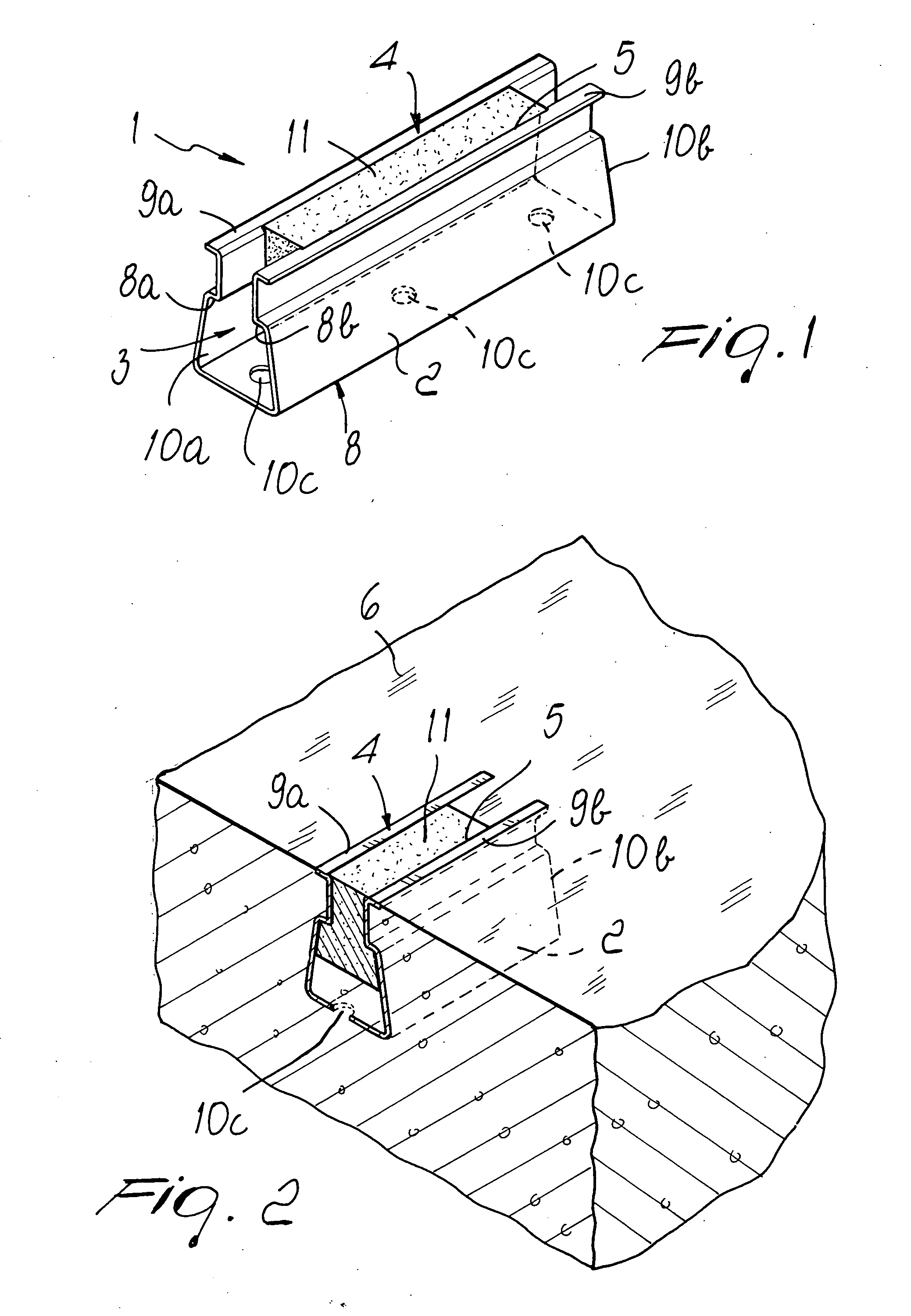
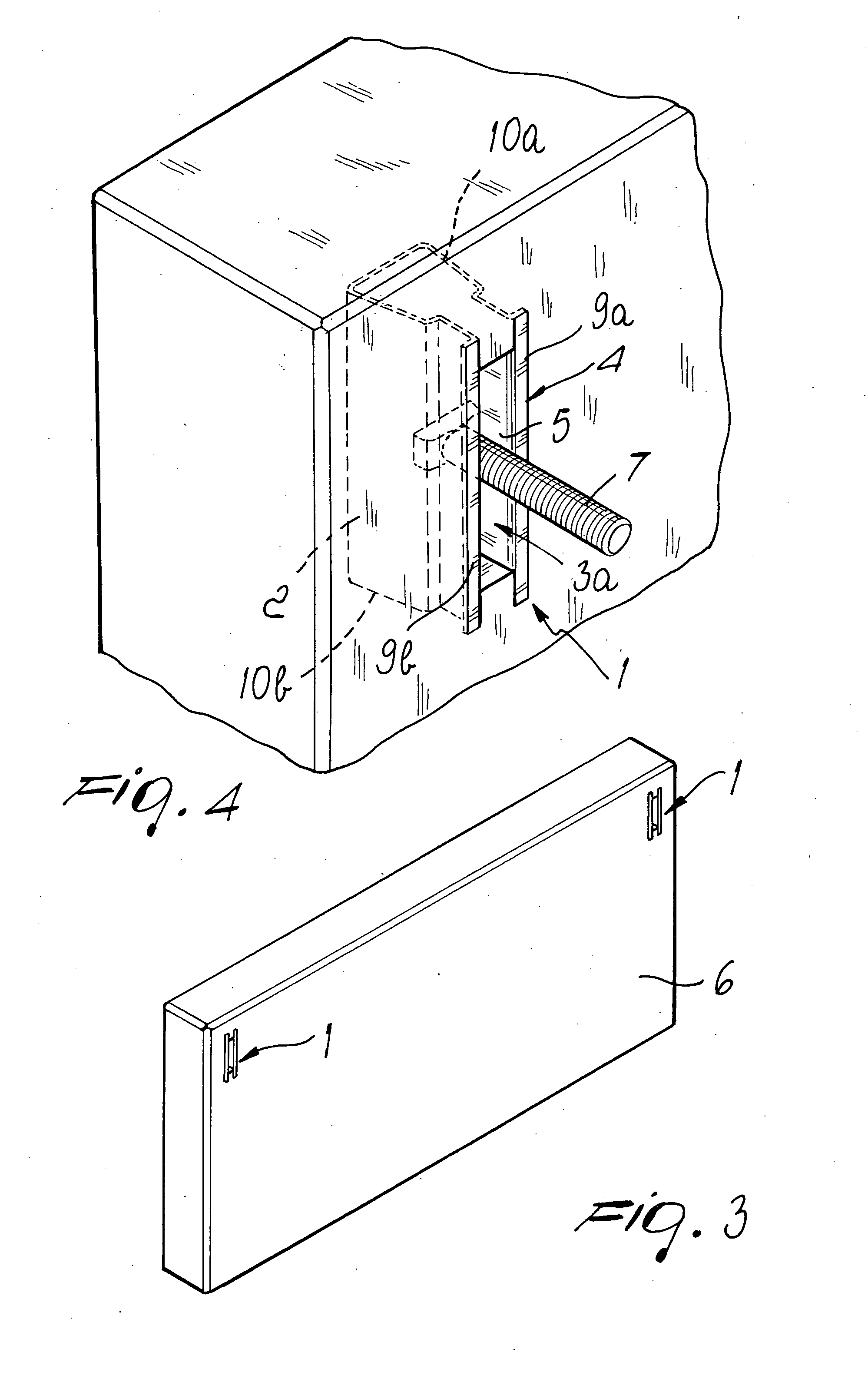
[0024] With reference to the figures, the anchoring insert according to the invention, generally designated by the reference numeral 1, comprises an insert body 2, which delimits a compartment 3 and is provided with a face 4 in which there is a main opening 5, which allows access to the compartment 3.

[0025] The anchoring insert 1 is designed to be embedded in the body of a concrete component 6 so that the face 4 is substantially flush with one face of the component and so that the remaining part of the insert is embedded in the body of the component 6.

[0026] It is possible to insert in the main opening 5, when the anchoring element 1 is embedded in the component 6, a connecting element 7 in order to connect the component 6 to other parts of a building. FIG. 4 illustrates a connecting element 7 constituted by the threaded portion of a bolt with a T-shaped head, but the connecting element 7 can also be constituted by a different connecting element of a known type.

[0027] According t...


PUM


Abstract

A concrete component embedded anchoring insert for bracing panels in buildings, and prefabricated concrete component provided therewith, the anchoring insert comprising an insert body delimiting a compartment and having a face with a main access opening. The insert body can be embedded in the concrete component so that the face is substantially flush with a face of the concrete component. A connecting element can be inserted in the main opening. The insert body has at least one secondary opening allowing concrete of the component body to enter the compartment, and a protection provided in the compartment adapted to prevent the concrete from accessing a portion of the compartment which is designed to receive the connecting element.

Description

[0001] The present invention relates to an anchoring insert to be embedded in prefabricated concrete components, particularly for bracing panels in buildings or for anchoring other elements, such as rails, utility raceways, machines or the like, to the component, and to a prefabricated concrete component provided with such anchoring insert. BACKGROUND OF THE INVENTION [0002] Anchoring inserts are known which are designed to be embedded within prefabricated concrete components and are also known commonly as “slotted inserts” or more simply as “slots”. [0003] These anchoring inserts are generally constituted by a box-like body, obtained simply by bending a metal plate or provided by welding a plurality of appropriately shaped metal plates, which generally has a substantially flat face, usually with a rectangular plan shape, crossed by an elongated slot. Such box-like body is embedded, during the manufacture of the prefabricated concrete component, within the body of the component so t...

Claims


Application Information

Patent Timeline
Patent Type & Authority Applications(United States)
IPC IPC(8): E04B1/38E04C5/00
CPCE04B1/4107
Inventor ZAMBELLI, SERGIOZAMBELLI, BENITO
Owner ZAMBELLI SERGIO
Learn More