Structure of meter

Inactive Publication Date: 2007-02-08
WANG CHING HUNG
View PDF7 Cites 4 Cited by
  • Summary
  • Abstract
  • Description
  • Claims
  • Application Information

AI Technical Summary

Benefits of technology

[0013] Another object of the present invention is to improve the illumination of the meter and make the light source uniform.
[0014] Another object of the present invention is to improve the ability of the meter ring to guide light.
[0015] In order to achieve the above objects, the present invention relates to an improved structure of meter, which comprises a casing provided with a meter ring and a transparent cover plate at one end, a circuit board provided in the casing and having a connecting unit for connecting to an external machine, a central processor provided on the circuit board for transmitting and controlling the signals transmission among individual unit and machine, a display unit connected to the central processor for displaying the condition of each machine, a correcting memory unit connected to the central processor for detecting and memorizing the operating signals from various machines, a driving control unit connected to the central processor for saving the required variations in signals from each machine, a monitoring unit connected to the central processor for presetting an alarm value and producing an alarm signal, a wireless transmitting unit connected to the central processor for receiving the signals transmitted from the wireless controller, and an illuminating unit connected to the central processor for corresponding to both ends of the meter ring and the display unit.

Problems solved by technology

However, in some cases, for example, the meter is not precise enough, the monitoring range is too small, or the operation is not convenient etc., it is necessary to install another meter to measure the desired data.
In the above situations, a case that there is error between the represented data and the actual data, or the user cannot determine the represented data will be inevitably happened.
Such a situation happens because the driving circuits or controlling programs of the monitoring meter are incompatible with the monitored instruments, or encryption has been made to the signal source of the instrument so that the meter cannot read the signal, causing the monitoring instrument to falsely determinate or unable to determine.
When a user needs to additionally install a speedometer whose range of the speed is 0˜220 km / h or a revolution meter whose range is 0˜9000 rpm, he will find that there is error between the results of this new revolution meter and those of the original revolution meter.
Therefore, when the detecting programs or driving signals of a monitoring instrument are designed based on general criteria, such instrument can only be used in some kinds of cars.
If such instrument is used in the cars designed by different criteria, false determination or inefficient determination can be happened.
However, there are so many kinds of meters that each kind of meter needs a different component and associated driving circuit.
Also, many components will prolong the manufacturing period.
However, in practice, such operation has great drawbacks.
That is, the meter cannot operate without a control box.
In other words, the user should additionally buy a control box so as to operate the meter, resulting in a burden to the consumer.
However, when illuminating, since the above light sources in the meter panel can only create lighting spots at certain points, the whole meter panel cannot be uniformly illuminated.
Although each method can perform the mass production, the manufacture has to store up many components to fit various kinds of meters, resulting in high cost.
Therefore, in practice, conventional meters cannot satisfy the above requirements.

Method used


Image

  • Structure of meter
  • Structure of meter
  • Structure of meter

Examples


first embodiment

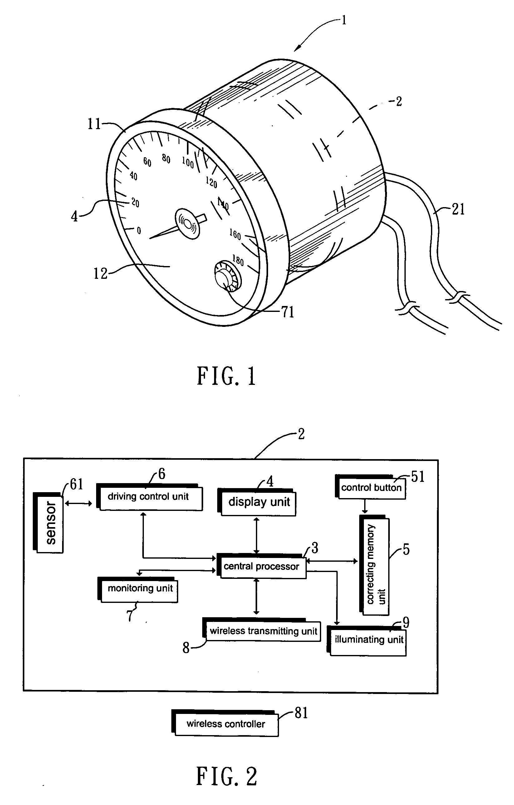
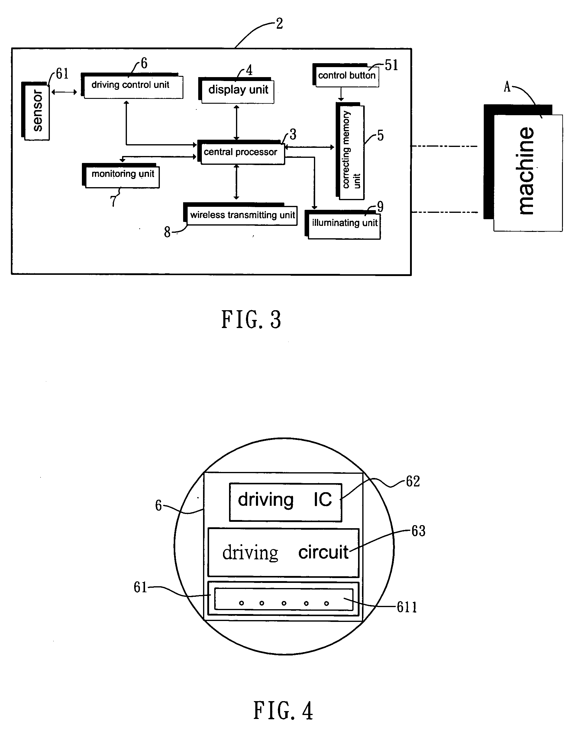
[0035]FIG. 3 is a schematic view of the present invention. As shown in the drawing, after the present invention is connected to an external machine A, the correcting memory unit 5 is used to perform the setting of various machines by the following steps: “multiplying”, “dividing”, “adding” or “subtracting” in the program for detecting signals; extracting the signal at a random point (or a specific point); making the signal as the base point, proportionally “multiplying”, “dividing”, “adding” or “subtracting” the remaining signals, and displaying the result after computing. When the signal source varies, the output of signals will also vary in proportion to such variation. As a result, no matter the forms for the signal source (number of pulse, voltage, resistance, or the like), all the signals can be correctly displayed after comparing and correcting.

[0036] For example, when the speed of a car is 100 km / h and the number of pulse is 10 Hz, it can be considered that the number of puls...

second embodiment

[0039]FIG. 4 is a schematic view of the present invention. As shown in the drawing, when using the driving control unit 6 of the present invention, the required variation of signals in the meter is input to the driving control unit 6 to form a database, and makes a driving IC 62. The components (such as resistor, capacitor, IC for regulating the voltage, diode, tantalum capacitor, ceramic capacitor etc.,) of the driving circuit 63 of the driving control unit 6 are provided on the same circuit board, and the signal input port of the sensor 61 can be a connector socket 611. According to the all data preset in the driving IC 62, the connector socket 611 of the sensor 61 can be defined as various signal pins, such as voltage signal, temperature signal and pressure signal. When the meter is intended to be used as a voltammeter, thermometer for water, or thermometer for oil, the sensor for detecting the voltage, water temperature, oil temperature of the external machine A should be connec...

third embodiment

[0040]FIG. 5 is a schematic view of the present invention. As shown in the drawing, the monitoring unit 7 of the present invention can be used in a meter for measuring the water temperature, oil pressure or the voltage depending on the setting of the central processor 3. When the monitoring unit 7 is actually used, the alarm temperature, pressure, voltage and suggesting points for alarm signal in each preset value can be set by the control button 71. Therefore, according to the input exclusive signals and the selection of the alarm control button, the meter can perform suitable actions corresponding to the demands of the user.


PUM


Abstract

An improved structure of meter, comprising a casing, a circuit board provided in the casing and having a connecting unit for connecting to an external machine, a central processor provided on the circuit board for transmitting the signals among individual unit and machine, a display unit for displaying the condition of the external machine, a correcting memory unit for detecting and memorizing the signals from various machines, a driving control unit for saving the variations in signals from various machines, a monitoring unit for presetting an alarm value and producing an alarm signal, a wireless transmitting unit for receiving the signals transmitted from the wireless controller, and an illuminating unit connected to the central processor for corresponding to both ends of the meter ring and the display unit. With the above arrangement, the meter of the present invention can be adapted to various kinds of machines and instruments.

Description

FIELD OF INVENTION [0001] The present invention relates to an improved structure of meter, and especially, to a structure of a multiple-function meter suitable for various kinds of machines. BACKGROUND OF THE INVENTION [0002] In daily life, various kinds of monitoring instruments are widely used, such as thermometers for measuring temperature, speedometers used in cars, or the like. However, in some cases, for example, the meter is not precise enough, the monitoring range is too small, or the operation is not convenient etc., it is necessary to install another meter to measure the desired data. In the above situations, a case that there is error between the represented data and the actual data, or the user cannot determine the represented data will be inevitably happened. Such a situation happens because the driving circuits or controlling programs of the monitoring meter are incompatible with the monitored instruments, or encryption has been made to the signal source of the instrum...

Claims


Application Information

Patent Timeline
IPC IPC(8): G08B21/00
CPCG01D11/28G07C7/00G01D13/26
Inventor WANG, CHING-HUNG
Owner WANG CHING HUNG
Why Eureka
Try Eureka