
Actuator

a technology of actuators and actuators, applied in the field of actuators, can solve the problems of increasing the cost of the device, the disadvantage of miniaturization of the device by a large-sized motor, and the difficulty of further increasing the rotational speed of the polygon mirror, etc., and achieves the effect of compact structure and large deflection angl

Inactive Publication Date: 2007-02-01
SEIKO EPSON CORP
View PDF7 Cites 19 Cited by
  • Summary
  • Abstract
  • Description
  • Claims
  • Application Information

AI Technical Summary

Benefits of technology

[0009] The present invention has been made in view of the above drawbacks. It is, therefore, an object of the present invention to provide an actuator which provides a large deflection angle with a compact structure even in a case of low-voltage driving.

Problems solved by technology

However, it is difficult to further increase a rotational speed of a polygon mirror.
Such a large-sized motor is disadvantageous to miniaturization of the device.
Further, use of such a polygon mirror needs a complicated structure and thus increases cost for the device.
Thus, it is difficult to achieve both of low-voltage driving and a wide movable range (large deflection angle).

Method used


Image

  • Actuator
  • Actuator
  • Actuator

Examples


Embodiment Construction

[0040] An actuator according to embodiments of the present invention will be described below with reference to FIGS. 2 through 10. Like or corresponding parts are denoted by like or corresponding reference numerals throughout drawings, and will not be described below repetitively.

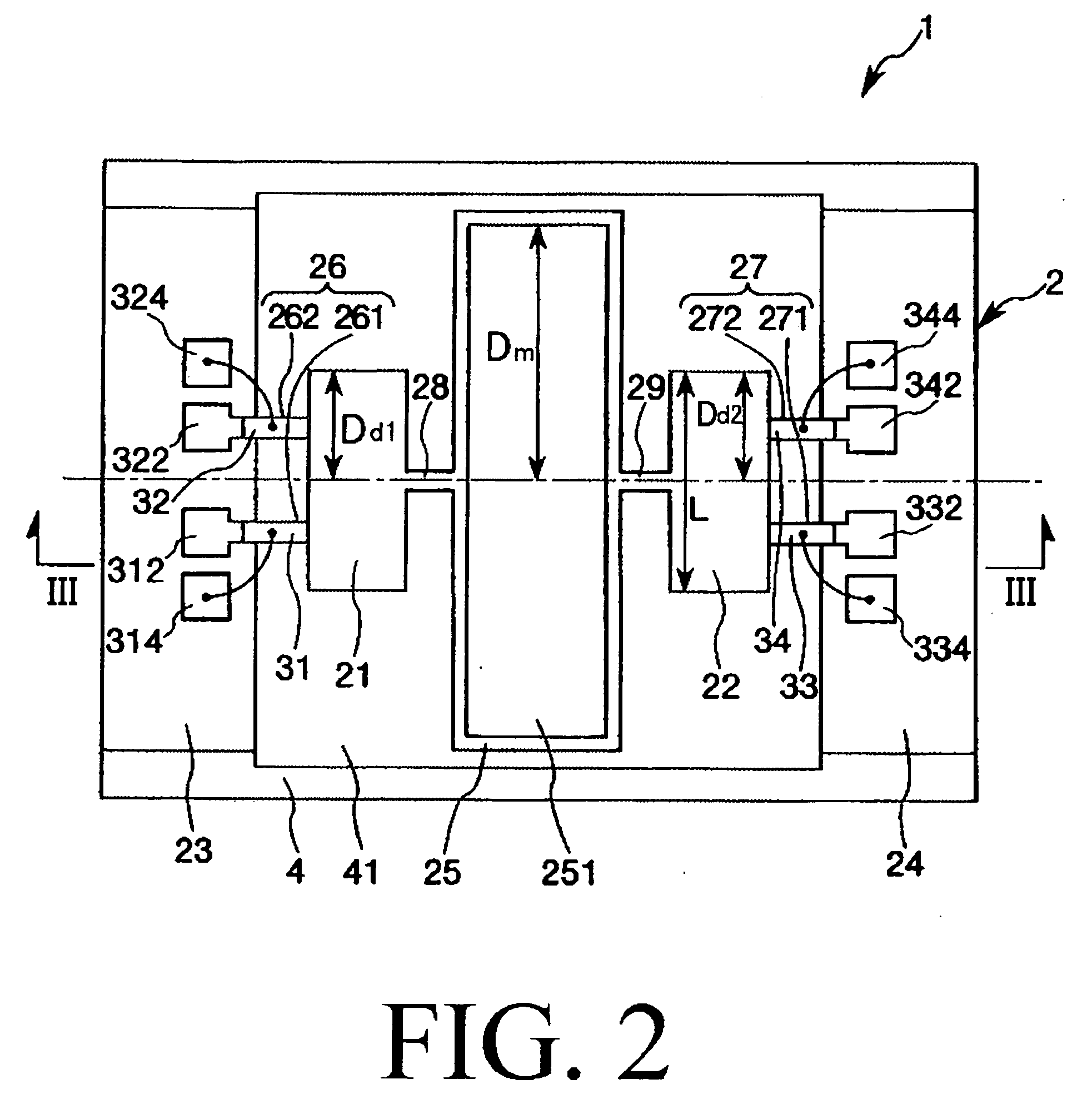
[0041]FIG. 2 is a plan view showing an actuator 1 according to a first embodiment of the present invention, and FIG. 3 is a cross-sectional view taken along line III-III of FIG. 2. In the following description, near, far, right, and left sides in FIG. 2 will be referred to as “upper,”“lower,”“right,” and “left,” respectively. Upper, lower, right, and left sides in FIG. 3 will be referred to as “upper,”“lower,”“right,” and “left,” respectively.

[0042] As shown in FIGS. 2 and 3, the actuator 1 includes a base member 2 having a two-degree-of-freedom vibration system, piezoelectric elements 31, 32, 33, and 34 for driving the two-degree-of-freedom vibration system of the base member 2, a bonding layer 5, and a ...


PUM


Abstract

The actuator has a movable mass portion and a pair of drive mechanisms for driving the movable mass portion. Each of the pair of drive mechanisms includes a drive mass portion, a support portion for supporting the drive mass portion, a first elastic connecting portion interconnecting the drive mass portion and the support portion so as to allow the drive mass portion to be pivoted about a pivotal axis with respect to the support portion, and a second elastic connecting portion interconnecting the drive mass portion and the movable mass portion so as to allow the movable mass portion to be pivoted about a pivotal axis with respect to the drive mass portion. The first elastic connecting portion includes a pair of bending bars opposed to each other with interposing the pivotal axis of the drive mass portion therebetween. The first elastic connecting portion includes a pair of piezoelectric elements jointed respectively onto the pair of bending bars so as to bend the pair of bending bars in opposite directions to cause pivotal movement to the drive mass portion. The pivotal movement of the drive mass portion causes torsional deformation to the second elastic connecting portion so as to pivot the movable mass portion.

Description

CROSS-REFERENCE TO RELATED APPLICATION [0001] This application claims priority to Japanese Patent Application No. 2005-182626 filed Jun. 22, 2006, which is hereby expressly incorporated by reference herein in its entirety. BACKGROUND OF THE INVENTION [0002] 1. Field of the Invention [0003] The present invention relates to an actuator, and more particularly to an actuator suitably used in an optical devices such as an optical scanner, an optical attenuator, and an optical switch. [0004] 2. Description of the Related Art [0005] For example, polygon mirrors (rotary polyhedrons) are used as actuators for devices such as laser printers. In order to achieve high-speed printing with high resolution and high quality, it is necessary to rotate a polygon mirror at higher speeds. Currently, an air bearing is used to rotate a polygon mirror at high speeds with stability. However, it is difficult to further increase a rotational speed of a polygon mirror. Additionally, a large-sized motor is req...

Claims


Application Information

Patent Timeline
Patent Type & Authority Applications(United States)
IPC IPC(8): G02B6/26
CPCG02B6/3512G02B6/3578Y10T74/10G02B26/0858G02B6/3594
Inventor YODA, MITSUHIRO
Owner SEIKO EPSON CORP
Learn More