
Method for making three-dimensional preforms using anaerobic binders

a three-dimensional preform and anaerobic technology, applied in the field of methods, can solve the problems of limiting the application of techniques, affecting the curing process, and affecting the curing effect so as to promote the curing of the curing process

Inactive Publication Date: 2007-02-01
AMERICAN GFM
View PDF20 Cites 56 Cited by
  • Summary
  • Abstract
  • Description
  • Claims
  • Application Information

AI Technical Summary

Benefits of technology

[0004] In making directed fiber preforms, it has heretofore been the practice to spray chopped fibers with a thermally-curable or thermally meltable binder resin onto a form that has air pulled therethrough to locate and hold the fibers. The form with the fibers and the binder resin is then heated or heated and cooled, rotated into a hot air plenum chamber, dried / cooled or cured to set the binder resin. This thermal curing process requires a great deal of energy, time and storage space for drying and curing the preforms. Improved methods based on the use of electromagnetic radiation-curable binders (“light-curable binders”) have been developed in U.S. Pats. Nos. 6,001,300, 6,004,123 and 5,866,060. Such techniques allow for more energy and time-efficient production of preforms by using the radiation-curable binders. Such binders are cured by applying directed energy, for instance ultraviolet or microwave radiation, thus dispensing with the need for large, continuously operating ovens for curing the binder.
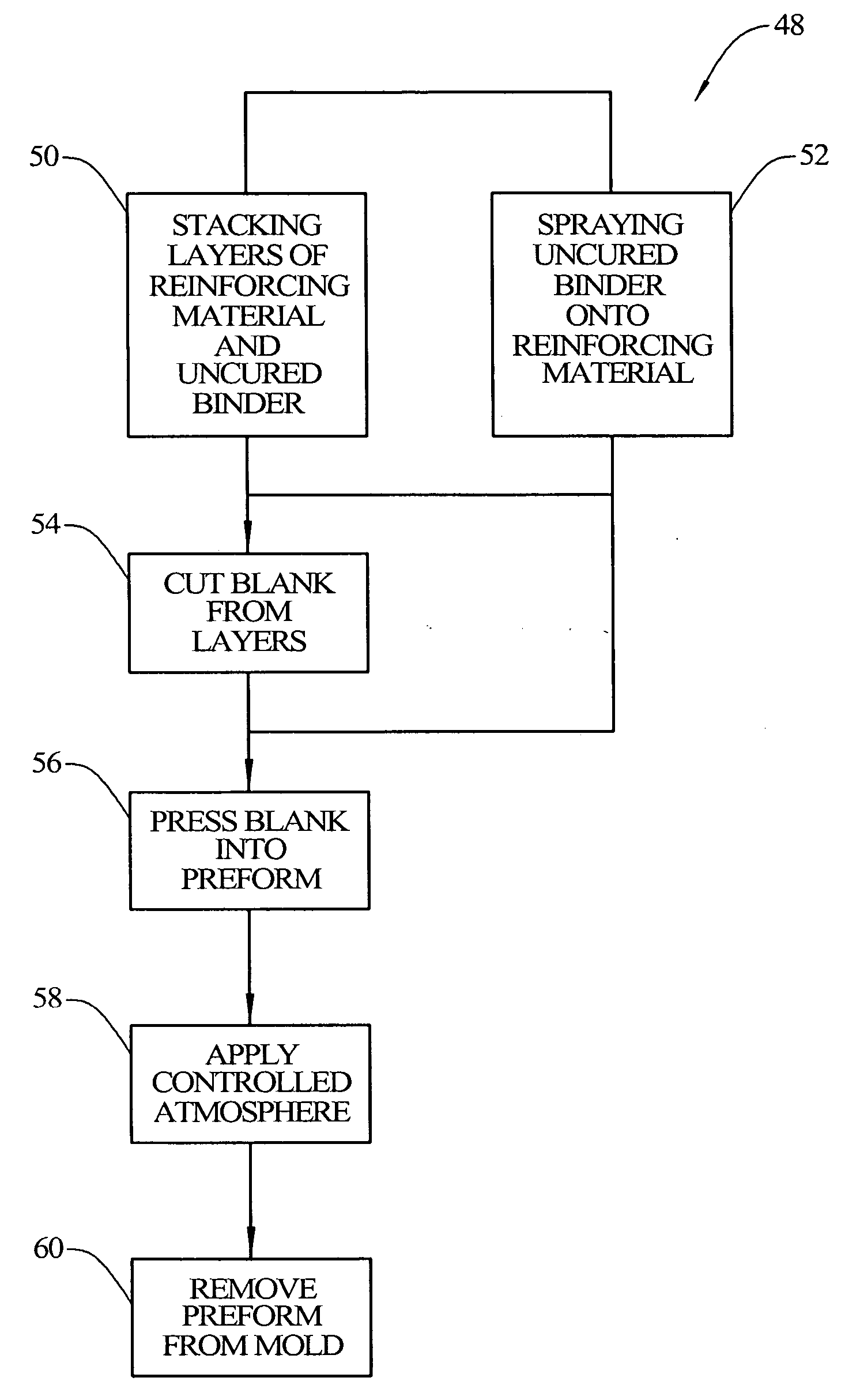
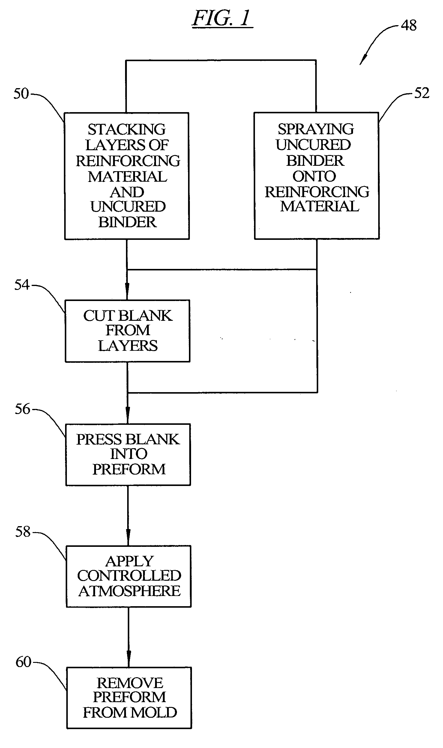
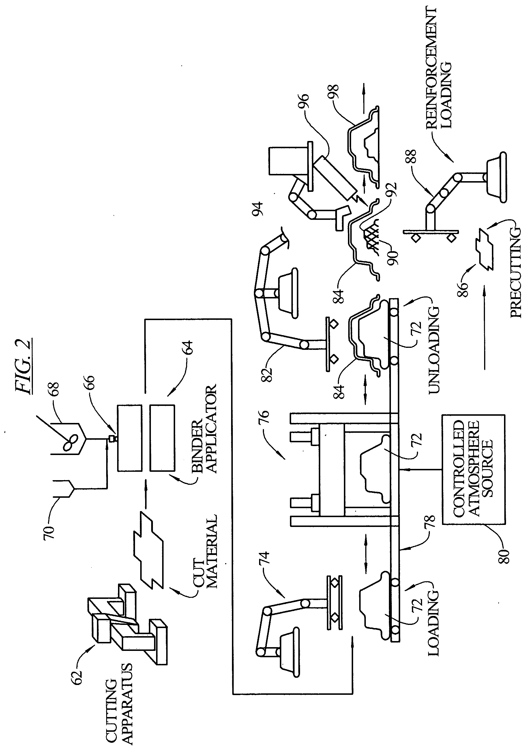
[0010] More embodiments of the invention provide a method of manufacturing a preform, comprising the steps of: moving a plurality of webs of fibrous reinforcing material along respective paths and guiding the webs superposed such that they superpose parallel to one another at a predetermined location and travel parallel to and in contact with one another; applying a two-stage binder comprising an anaerobic component and an electromagnetic radiation-curable component to at least one surface of each pair of facing surfaces of the webs upstream of the predetermined location, or separately applying an electromagnetic radiation-curable binder and an anaerobic binder to at least one surface of each pair of facing surfaces of the webs upstream of the predetermined location; locally applying electromagnetic radiation into selected spaced locations of the parallel contacting webs to cure the electromagnetic radiation-curable binder at the spaced locations and thereby tack the webs together; cutting a blank from the tacked webs; forming the blank in a three-dimensional shape corresponding to at least a portion of the preform; and contacting the blank with an atmosphere that promotes the curing of the anaerobic binder.
[0012] In some additional embodiments, the present invention provides a method for making a rigid three-dimensional structural preform using a separable mold including a perforate first mold part and a pressing second mold part, the mold parts, when closed, together defining a desired three-dimensional shape of the preform and including inner surfaces disposed at angles with respect to one another forming inside and outside corners, comprising the steps of cutting fibers of reinforcement material; propelling the cut fibers onto the perforate first mold part while contemporaneously flowing air through the first mold part to direct the fibers onto all surfaces of the first mold part to a predetermined thickness; applying an anaerobic binder onto the cut fibers to at least partially coat the fibers with the binder, without filling interstices among the fibers; closing the separable mold parts to press the binder-coated cut fibers into the desired three-dimensional shape of the preform between the pressing second mold part and the perforate first mold part of the closed mold; and applying to the anaerobic binder an atmosphere that promotes the curing of said binder.

Problems solved by technology

This thermal curing process requires a great deal of energy, time and storage space for drying and curing the preforms.
The applicability of the techniques is however limited when materials impervious to electromagnetic radiation are to be incorporated in the preform, for example core materials such as honeycomb or foam.
Certain fiber materials, such as Aramid, are also a challenge, because they effectively screen the light wavelengths that cure currently available light-curable binders.
The challenge is greater yet with materials such as carbon fiber materials, which block the access of radiation of any frequency in a range that is commercially available or practical at this time.
Preforms of carbon fibers alone cannot be made because the light will not penetrate multiple carbon fiber layers.

Method used


Image

  • Method for making three-dimensional preforms using anaerobic binders
  • Method for making three-dimensional preforms using anaerobic binders
  • Method for making three-dimensional preforms using anaerobic binders

Examples


Embodiment Construction

[0038] The present teachings provide new methods for manufacturing preforms, wherein the binder resin is an anaerobic binder. With these anaerobic methods preforms can be produced to any thickness where light curing would have to be used in several steps, or where light curing would not work such as with carbon fibers and with any medium that blocks light such as certain types of core materials. Since anaerobic curing is not directional, the materials, with the binder in place, can be assembled in the desired organization (laminate schedule) to any thickness and the preform is stabilized by applying an atmosphere promoting the curing of the anaerobic binder.

[0039] For example, a preform can now be produced in one step with combinations of many layers of carbon fiber, glass fibers, core materials, and metal inserts where the carbon, core materials and metal inserts would block the application of light, thus requiring more than one light-curing step, and where these materials would a...


PUM

PropertyMeasurementUnit
Fractionaaaaaaaaaa
Fractionaaaaaaaaaa
Percent by massaaaaaaaaaa

Abstract

The present invention relates to methods of making fiber-reinforced molded articles and fiber mats, wherein the methods use, inter alia, anaerobic binders.

Description

INTRODUCTION [0001] The present invention is related to a method and to an apparatus for making structural reinforcement preforms for various liquid composites processes such as resin transfer molding (RTM) and reaction injection molding (SRIM) processes for structural composites wherein a resin matrix as a deformable plastic material is filled into the interstices between the fibers of the formed structural reinforcement preforms when the preforms and plastic material are molded in a mold to form a structural composite comprising the plastic with the fibers contained therewithin as reinforcement. [0002] The present invention is further related to the handling of reinforcement webs used in the process and in attaching reinforcement members and the like as a part or parts of the preforms. [0003] The present invention additionally relates to two-stage binders, a mat making and preforming process, and to apparatus for carrying out the process, for curing binders on non-woven reinforcin...

Claims


Application Information

Patent Timeline
IPC IPC(8): B29C35/08B29C70/44
CPCB29B11/16B29C70/345C09J4/00B29C70/543B29C70/545B29C70/386
Inventor BUCKLEY, DANIEL T.
Owner AMERICAN GFM
Learn More