Flow meter and method

a flow meter and flow rate technology, applied in the direction of instruments, volume/mass flow by dynamic fluid flow effect, measurement devices, etc., can solve the problems of costly known fie testing equipment and lack of resolution of diesel engine injection events, and achieve accurate quantitative flow data and accurate measurement of flow rates

Inactive Publication Date: 2007-02-01
MICHIGAN CUSTOM MACHINES
View PDF4 Cites 9 Cited by
  • Summary
  • Abstract
  • Description
  • Claims
  • Application Information

AI Technical Summary

Benefits of technology

[0006] The invention relates to a new method and a new apparatus to accurately measure flow rates in injection systems such as gasoline, direct injection gasoline and diesel downstream of the injector where the fuel (liquid in general) is discharged from a nozzle (e.g. an injector). More specifically, it measures the flow velocities and volumetric flow rates in highly transient flows discharged cyclically with injection duration within a few hundred microseconds. Moreover, it is able to resolve multiple injection shots produced within an engine cycle with high volumetric (0.01 mm3) and temporal (10 μs) sensitivities. The main uses of this instrument in automotive industry are manufactures of FIE, injection test machines and injection diagnostic systems. In other industries the uses maybe represented by measuring and controlling of highly transient flows with a need to accurately perform quantitative flow data in wide range of timing and dosing.

Problems solved by technology

Moreover, known FIE testing equipment lacks the resolution to distinguish between injection events that occur in diesel engines.
Lastly, known FIE testing equipment is costly meaning that it may not be available to small companies, creating a barrier to entering the market of providing testing services.

Method used


Image

  • Flow meter and method
  • Flow meter and method
  • Flow meter and method

Examples


Embodiment Construction

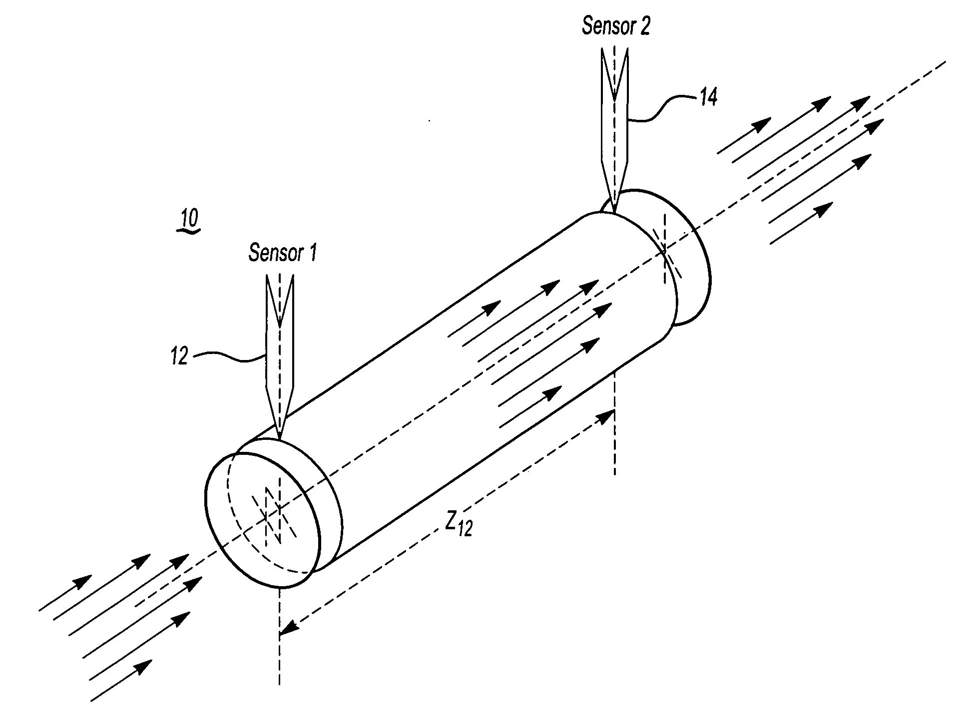
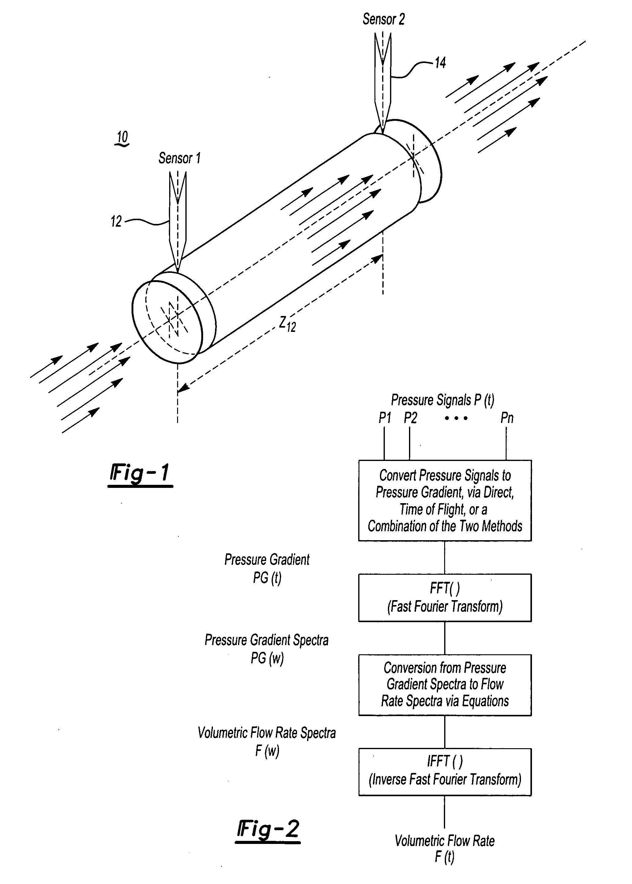
[0010] The present invention comprises a flow meter having at least one conduit through which a fluid can flow. The conduit generally has a circular cross-section, although other cross sections are also suitable (e.g. oval). The length of the conduit is not particularly critical, although lengths shorter than about 1 foot are preferred with a length of less about than 6 inches being most preferred. Although use of a single conduit is preferred, several conduits may be used in conjunction with each other to form a flow meter.

[0011] The flow meter of the present invention is suitable for analyzing a wide range of fluids, but finds a particular application in the automotive area, and in particular, for analyzing the flow of fuels. For example, fuel injectors for automotive engines may be connected to the flow meter to determine the amount of fuel emitted by the injector. The flow meter generally measures the propagation of the fluid down the conduit by detecting the fluid or a changin...


PUM


Abstract

The invention relates to a new method and a new apparatus to accurately measure flow rates in injection systems such as gasoline, direct injection gasoline and diesel downstream of the injector where the fuel (liquid in general) is discharged from a nozzle (e.g. an injector). More specifically, it measures the flow velocities and volumetric flow rates in highly transient flows discharged cyclically with injection duration within a few hundred microseconds. Moreover, it is able to resolve multiple injection shots produced within an engine cycle with high volumetric (0.01 mm3) and temporal (10 μs) sensitivities. The main uses of this instrument in automotive industry are manufactures of FIE, injection test machines and injection diagnostic systems. In other industries the uses maybe represented by measuring and controlling of highly transient flows with a need to accurately perform quantitative flow data in wide range of timing and dosing.

Description

CLAIM OF PRIORITY [0001] This application claims the benefit of U.S. provisional application Nos. 60 / 650,347, filed Feb. 4, 2005 and 60 / ______, (Attorney Docket No. 1204.002P2), filed Feb. 1, 2006, both of which are here by incorporated by reference.FIELD OF THE INVENTION [0002] The present invention relates to apparatuses and methods for measuring quantities of flowing fluids, and more particularly, to an improved flow meter and methods of using the flow meter. BACKGROUND OF THE INVENTION [0003] In the automotive field, fuel injection equipment (FIE) needs to be quantitatively tested in terms of timing of injection events and injection volume; sometimes called dosing. For diesel engines, the requirements of temporal resolution and dosing accuracy are increased because of multiple injections per cycle are used to increase fuel efficiency and to reduce emissions, especially soot and NOx. [0004] Known FIE testing equipment is limited to injection volumes that range only over an order ...

Claims


Application Information

Patent Timeline
Patent Type & Authority Applications(United States)
IPC IPC(8): G01F1/22G01F1/7082
CPCG01F1/666G01F1/712G01F1/7082
Inventor PALAZZOLO, FRANKISMAILOV, MURAD M.
Owner MICHIGAN CUSTOM MACHINES
Why Eureka
Try Eureka