Removable, multi-purpose utility light for motor vehicles

a multi-purpose, auxiliary lighting technology, applied in the direction of other compartment lighting, portable lighting devices, lighting and heating apparatus, etc., can solve the problem of not always desirabl

Inactive Publication Date: 2007-01-25
MOTOTRIX
View PDF25 Cites 21 Cited by
  • Summary
  • Abstract
  • Description
  • Claims
  • Application Information

AI Technical Summary

Benefits of technology

[0006] The present invention provides many strategies for improving auxiliary lighting for motor vehicles, wherein these strategies may be implemented singly or in combination. The lighting system of the invention may be very compact. It is easy to mount and remove from a vehicle. Assembly and disassembly of parts during mounting and removal is not needed. Additionally, rather than mounting to a trailer hitch with external wiring coupling the hitch-mounted item to the electrical system of the vehicle, the lighting system of the invention may be configured so that it both mounts to and draws power from a socket on the vehicle. This easily allows all wiring to be internally housed and protected from the elements. Mounting is very easy. Simply mount and plug the system into the vehicle socket and it is ready for use. Simply pull the system out and it is ready for storage.
[0007] Notwithstanding the compactness of some embodiments, the lighting systems may use one or more elegantly simple heat management strategies to help dissipate heat generated during operation. In some modes, using lower wattage light bulbs may minimize this heat output. However, this is not always desirable, as lower wattage bulbs may not produce the desired degree of illumination. Advantageously, the heat management strategies of the present invention allow higher wattage bulbs to be used, if desired, without undue heat build up. As one strategy, at least one reflector has a relatively long neck, or body, extending backward away from the light emitting element. When thermally coupled to the lighting, the long neck functions as a passive heat sink to convey heat away from the lighting. The housing optionally may be vented to further help carry the heat away from the heat sink. Additionally, the light emitting element is encased in an envelope that helps a heat reflecting surface direct heat outward through the lens cover and away from the unit. For extra compactness, the heat reflecting surface and a light reflecting surface may be integrated into the same reflector element.
[0008] A user may easily switch among two or more operational modes. For instance, the lighting system may include a reverse / back up mode that provides illumination when a vehicle is placed into reverse gear. Alternatively, the system may include a utility mode that provides illumination when the parking lights of the vehicle are turned on. In preferred modes, the user may select among available modes simply by relative rotational motion among housing components.

Problems solved by technology

However, this is not always desirable, as lower wattage bulbs may not produce the desired degree of illumination.

Method used


Image

  • Removable, multi-purpose utility light for motor vehicles
  • Removable, multi-purpose utility light for motor vehicles
  • Removable, multi-purpose utility light for motor vehicles

Examples


Embodiment Construction

[0070] The embodiments of the present invention described below are not intended to be exhaustive or to limit the invention to the precise forms disclosed in the following detailed description. Rather the embodiments are chosen and described so that others skilled in the art may appreciate and understand the principles and practices of the present invention.

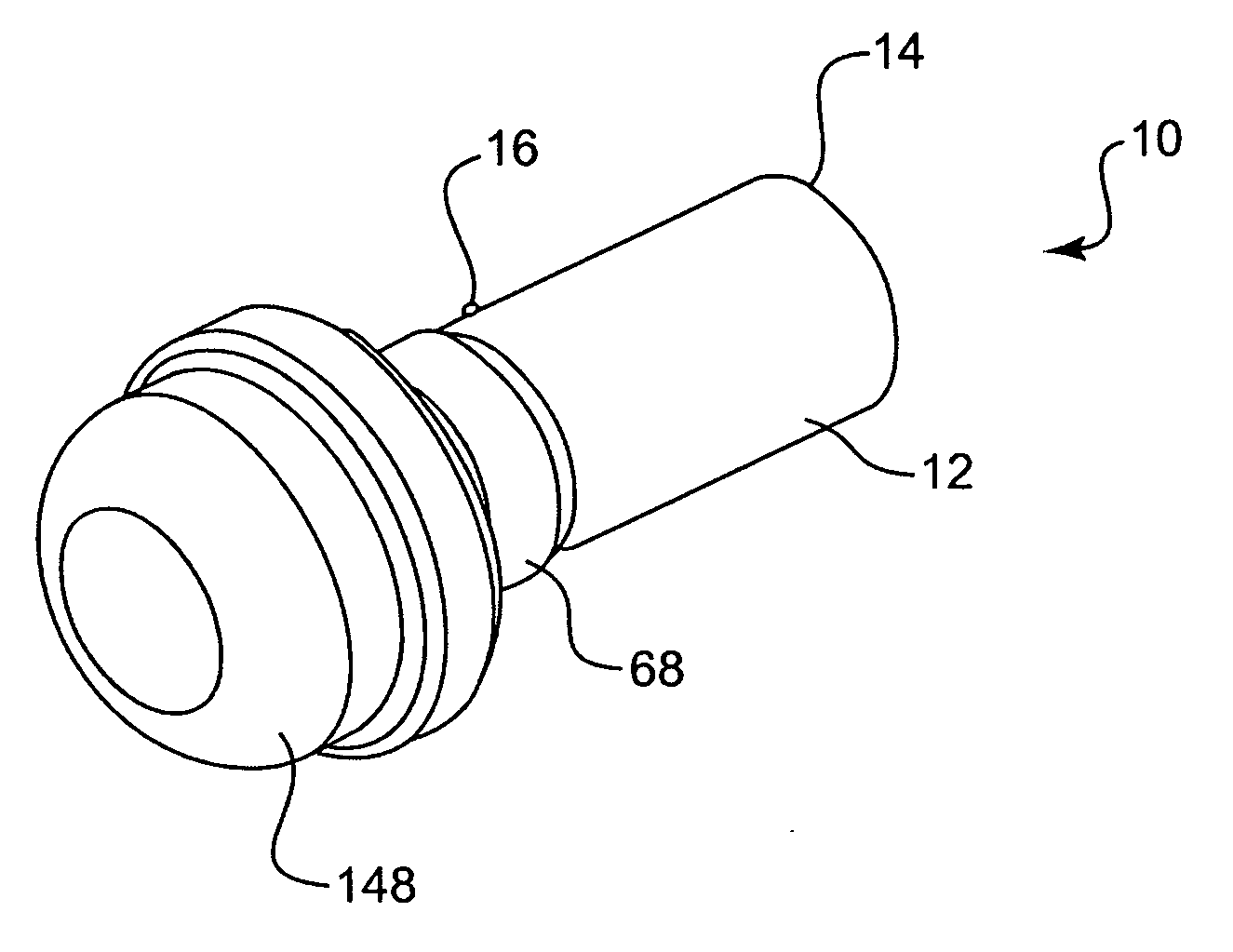
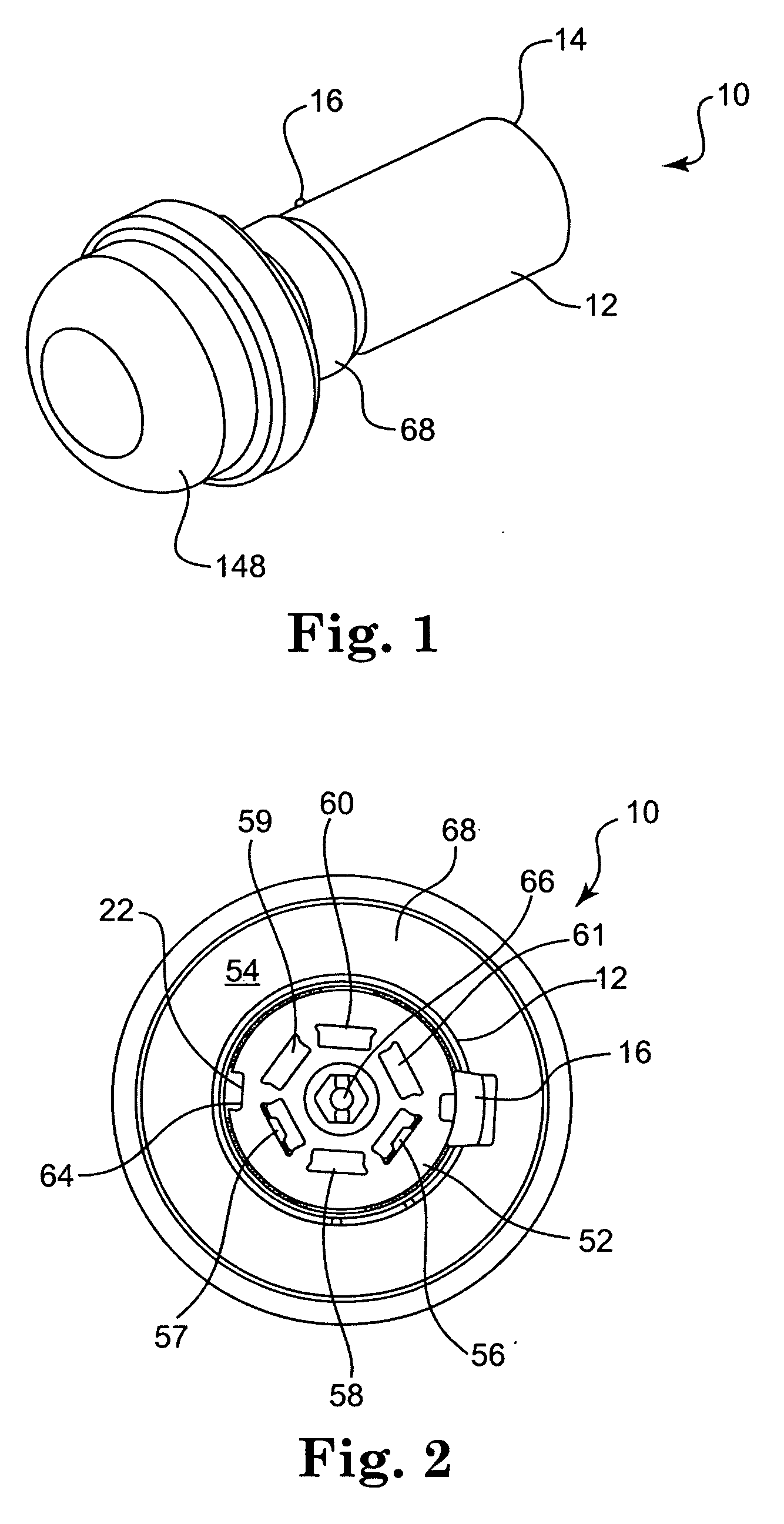
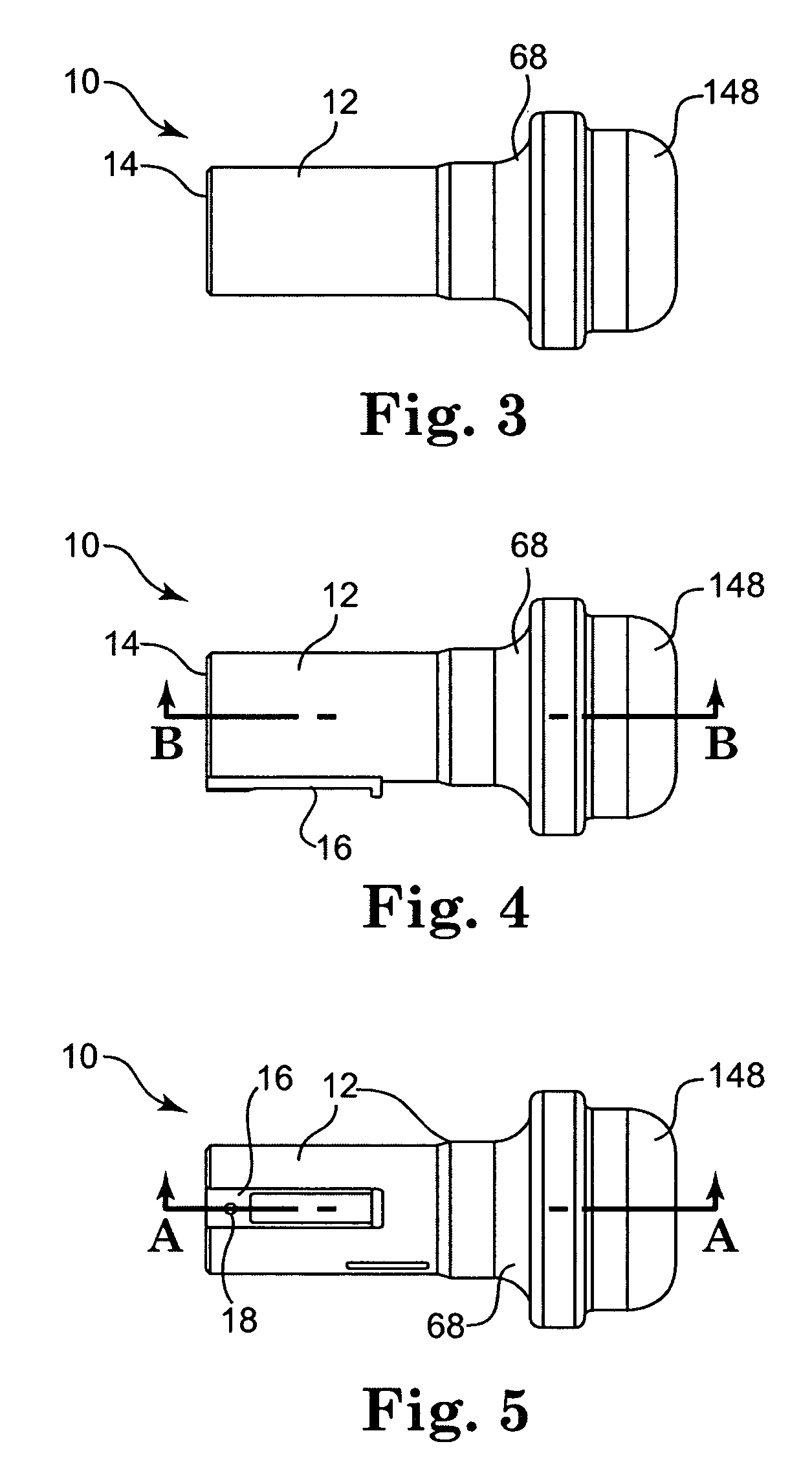
[0071]FIGS. 1 through 30 show an illustrative embodiment of a light assembly 10 incorporating principles of the present invention. The light assembly 10 includes a housing formed from at least two housing elements. The housing in the preferred embodiment shown in FIGS. 1 through 30 includes main body 12, switch body 68, and cover 148. For purposes of illustration, body 12 is generally tubular in shape. Main body 12 extends from a first end 14 to a second end 24. In this preferred embodiment, first end 14 of main body 12 is configured for direct insertion and mounting to a conventional, seven-way, round trailer electrical socket ...


PUM


Abstract

Auxiliary lighting for motor vehicles. The lighting system of the invention may be configured so that it both mounts to and draws power from a socket on the vehicle. The lighting systems may use one or more heat management strategies to help dissipate heat generated during operation. A user may easily switch among two or more operational modes. In preferred modes, the user may select among available modes simply by relative rotational motion among housing components. Some aspects of the invention also use a combination of reflecting elements that provide a very favorable pattern of illumination. According to one such embodiment, a primary reflector includes a dichroic surface that reflects some light outward, but allows some light to pass. A secondary reflector is then used to capture and reflect the passing light outward as well.

Description

CLAIM OF PRIORITY [0001] The present non-provisional patent Application claims priority under 35 USC §119(e) from U.S. Provisional Patent Application having Ser. No. 60 / 698,648, filed on Jul. 12, 2005, by Christopher Kregness and Harry Waite Webster, Jr., and titled REMOVABLE DUAL PURPOSE REVERSE AND UTILITY LIGHT FOR MOTOR VEHICLES, wherein the entirety of said provisional patent application is incorporated herein by reference.FIELD OF THE INVENTION [0002] The present invention relates to auxiliary lighting for vehicles. More specifically, the present invention relates to multi-purpose auxiliary lighting that provides illumination depending upon a state of the vehicle. For example, the lighting can provide illumination when the vehicle is placed into reverse and / or provide utility illumination whenever the vehicle running or parking lights are turned on. BACKGROUND OF THE INVENTION [0003] Motor vehicles have both front and reverse lighting systems. Front lighting normally uses rela...

Claims


Application Information

Patent Timeline
IPC IPC(8): F21S8/00
CPCB60Q1/24F21V29/505F21V29/004B60Q3/065B60Q3/35F21V29/70
Inventor KREGNESS, CHRISTOPHER A.WEBSTER, HARRY W. JR.
Owner MOTOTRIX
Why Eureka
Try Eureka