
CPP-GMR sensor with non-orthogonal free and reference layer magnetization orientation

a reference layer and magnetization orientation technology, applied in the field of magnetic heads, can solve the problems of limited sensor output, unfavorable scale, and the inability of cip-sv sensor technology to extend to the size of the sensor at/near or below roughly 50 nm

Inactive Publication Date: 2007-01-25
HITACHI GLOBAL STORAGE TECH NETHERLANDS BV
View PDF3 Cites 40 Cited by
  • Summary
  • Abstract
  • Description
  • Claims
  • Application Information

AI Technical Summary

Benefits of technology

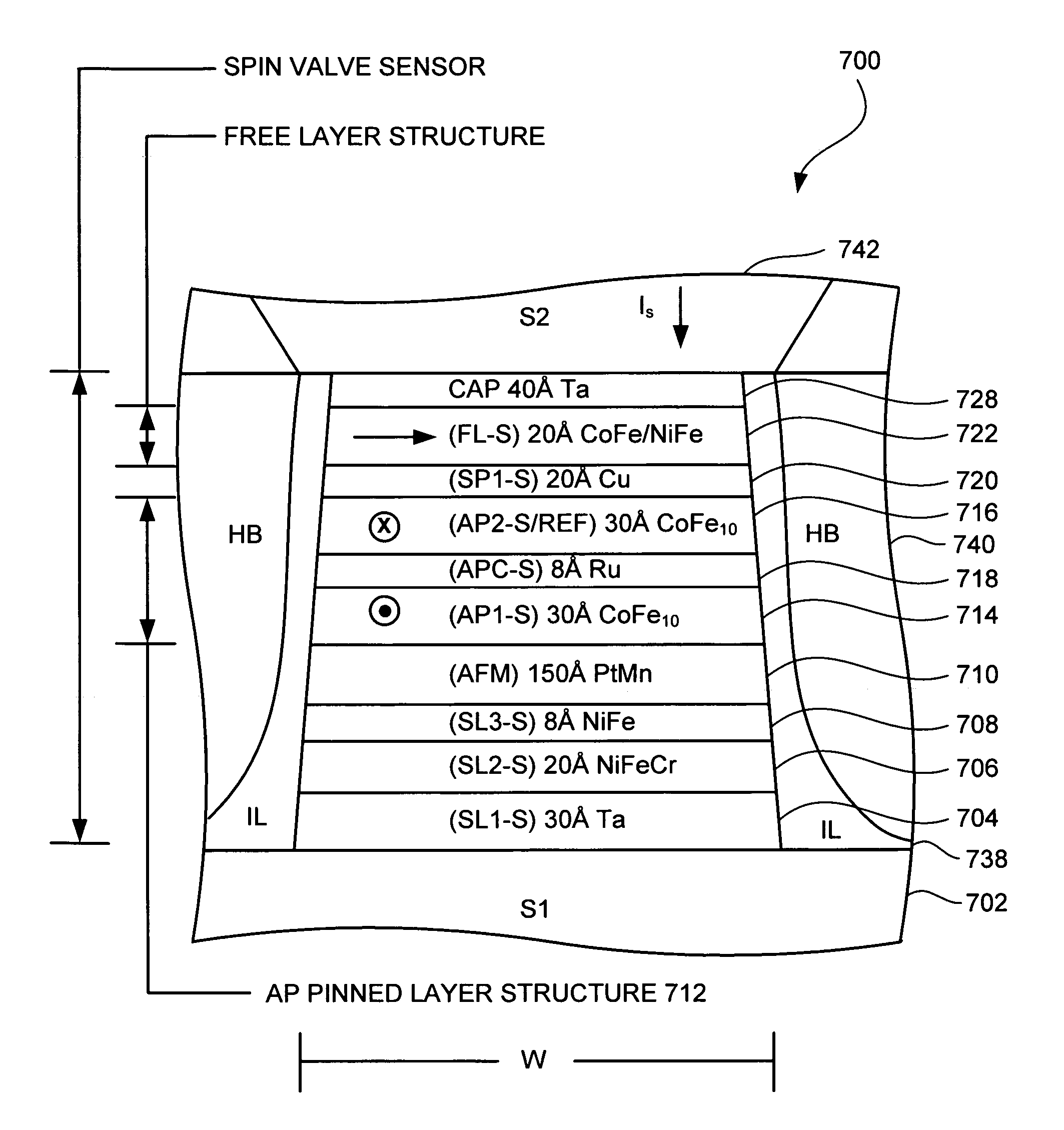
[0020] As mentioned above, for CIP sensors, the (in-plane) angular magnetization orientations θr and θfb of the reference and free layer structures at the bias point are ideally orthogonal each other, such that |θfb−θr|≅90°. However, as indicated in the graph of FIG. 2B, CPP sensors show magnetoresistance that is nonlinear in the quantity Q=cos(θf−θr).

Problems solved by technology

Because the bias voltage limitations due to Joule heating, the sensor output will be limited by the ratio of Rint / (Rint+Rpar) which scales unfavorably as sensor size is reduced.
Due to this, along with fabrication difficulty associated in lithographic limitations in forming the electrical junctions and maintaining robust electrical insulation from the shields, it is projected that CIP-SV sensor technology will not be extendable to sensor sizes at / near or below roughly 50 nm.
Of these two, TMR sensors have to date received the most immediate attention and development for the first generation of CPP read heads, due to their potentially very large ΔR / R0>>10% However, the large resistance area product (RA) of TMR tunnel barriers (˜2 Ω-μm2) would predict prohibitively large device impedances RA / (TW×SH) in the ˜50 nm device size regime.
It is believed that this aspect of CPP-SV and its consequences on bias point optimization has heretofore not been fully appreciated to the magnetic head community.

Method used


Image

  • CPP-GMR sensor with non-orthogonal free and reference layer magnetization orientation
  • CPP-GMR sensor with non-orthogonal free and reference layer magnetization orientation
  • CPP-GMR sensor with non-orthogonal free and reference layer magnetization orientation

Examples


Embodiment Construction

[0043] The following description is the best embodiment presently contemplated for carrying out the present invention. This description is made for the purpose of illustrating the general principles of the present invention and is not meant to limit the inventive concepts claimed herein. Further, particular features described herein can be used in combination with other described features in each of the various possible combinations and permutations.

[0044] Referring now to FIG. 3, there is shown a disk drive 300 embodying the present invention. As shown in FIG. 3, at least one rotatable magnetic disk 312 is supported on a spindle 314 and rotated by a disk drive motor 318. The magnetic recording on each disk is in the form of an annular pattern of concentric data tracks (not shown) on the disk 312.

[0045] At least one slider 313 is positioned near the disk 312, each slider 313 supporting one or more magnetic read / write heads 321. As the disks rotate, slider 313 is moved radially in ...


PUM


Abstract

A CPP GMR sensor structure having free and reference layers, where the magnetic orientations of the free and reference layers are non-orthogonal. In one embodiment, a ferromagnetic free layer film has a bias-point magnetization nominally oriented in plane of the film thereof, in a first direction at an angle θfb with respect to a longitudinal axis being defined as the intersection of the plane of deposition of the free layer and the plane of the ABS. A ferromagnetic reference layer film has a bias-point magnetization nominally oriented in a plane of the film thereof, in a second direction at angle θrb with respect to said longitudinal axis that is not orthogonal to the said first direction.

Description

RELATED APPLICATIONS [0001] This application claims priority to U.S. Provisional Patent Application Ser. No. _______, filed Jul. 18, 2005 and entitled “Thermal and Spin-Torque Noise in CPP (TMR and / or GMR) Read Sensors” to Smith et al. and which is herein incorporated by reference.FIELD OF THE INVENTION [0002] The present invention relates to magnetic heads, and more particularly, this invention relates to a Current-Perpendicular-to-Plane (CPP) Giant Magnetoresistance (GMR) head having nonorthogonal alignment of free and reference layer magnetizations. BACKGROUND OF THE INVENTION [0003] The heart of a computer is a magnetic disk drive which includes a rotating magnetic disk, a slider that has read and write heads, a suspension arm above the rotating disk and an actuator arm that swings the suspension arm to place the read and write heads over selected circular tracks on the rotating disk. The suspension arm biases the slider into contact with the surface of the disk when the disk is...

Claims


Application Information

Patent Timeline
IPC IPC(8): G11B5/127G11B5/33
CPCB82Y25/00G01R33/093H01L43/08G11B5/3932G11B2005/0016G11B5/3903H10N50/10
Inventor CHILDRESS, JEFFREY ROBINSONSMITH, NEIL
Owner HITACHI GLOBAL STORAGE TECH NETHERLANDS BV
Learn More