Position information service providing system and method thereof
a technology of location information and information service, applied in the field of location based information service providing system, can solve the problem of long waiting time of users b>209/b>, and achieve the effect of reducing the waiting time users feel when a location based information service is provided
- Summary
- Abstract
- Description
- Claims
- Application Information
AI Technical Summary
Benefits of technology
Problems solved by technology
Method used
Image
Examples
embodiment 1
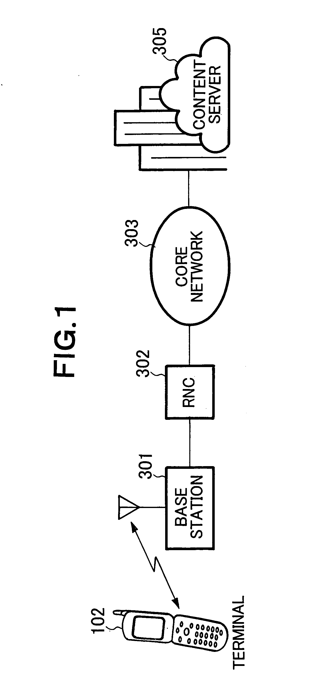
[0089] A first embodiment of the present invention will now be described. Structure of a system according to the present embodiment is the same as that shown in FIG. 1 which has already been described.
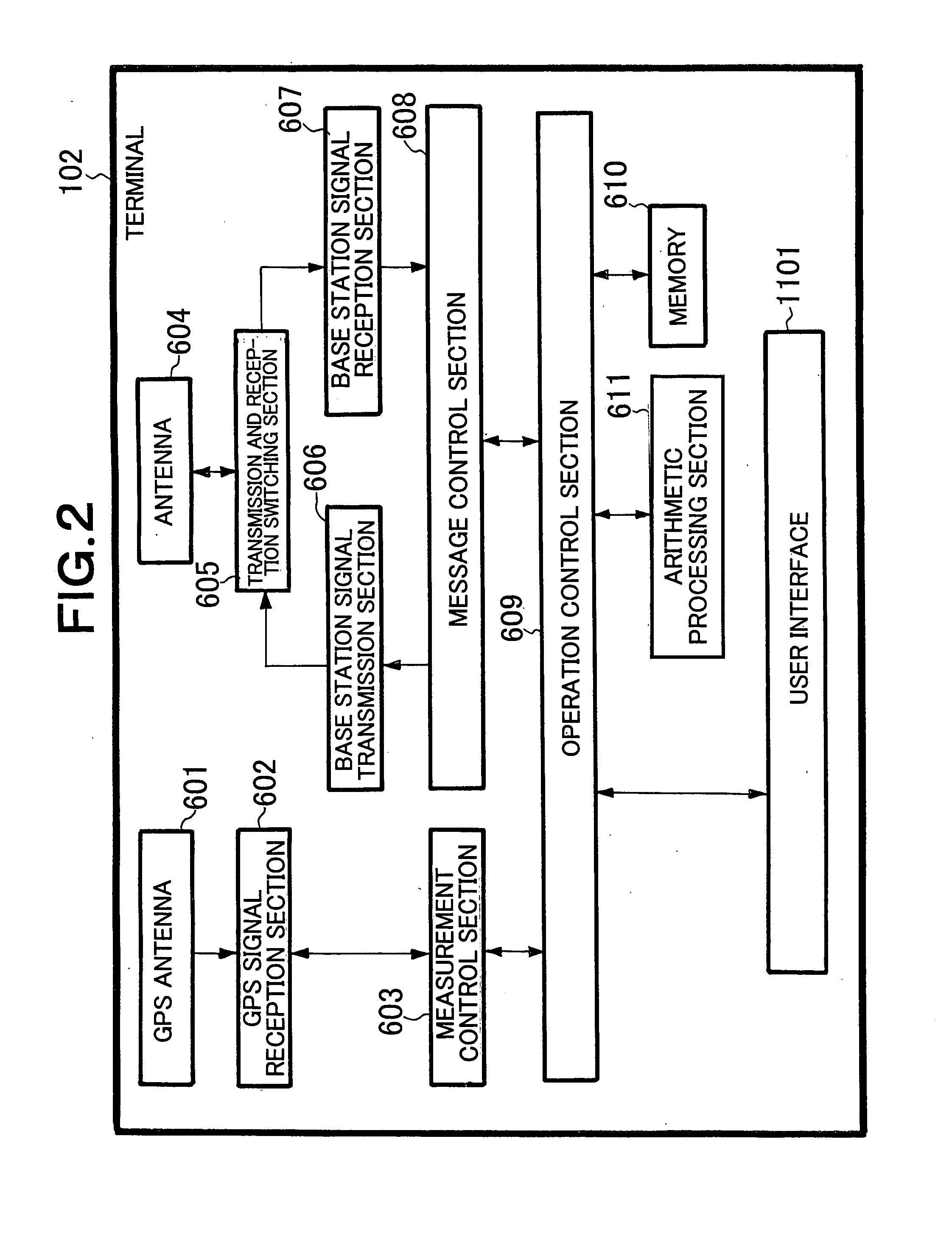
[0090]FIG. 6 is a block diagram of a terminal 102. The same components of the structure as those shown in FIG. 2 are denoted by the same numerals, and detailed descriptions thereof will be omitted.
[0091] The structure of the terminal 102 shown in FIG. 6 differs from the structure shown in FIG. 2 in that the structure of FIG. 6 includes a recognition section 612. The recognition section 612 recognizes that the user 101 has clicked a link to a specific URL.
[0092]FIG. 7 is a chart showing a sequence between the terminal 102 and a content server 201 in the first embodiment of the present invention.
[0093] The user 101 clicks a link to a specific URL (step 501). A portal site that compiles services can be considered as the specific URL. Specifically, the link to the specific URL is descr...
embodiment 2
[0100] Next, a second embodiment of the present invention will be described.
[0101] In the first embodiment, the location measurement processing is started when a link to a specific URL is clicked by the user 101. The second embodiment will be described with reference to configuration in which the location measurement processing is started when a specific keyword included in a content received from the content server 201 is detected. Also in this embodiment, FIG. 6 is referred to as a block diagram depicting the terminal 102 like in the first embodiment.
[0102] In the present embodiment, the recognition section 612 recognizes that the content from the content server 201 includes a location measurement request “?gps_start”.
[0103]FIG. 8 is a chart showing a flow of a content between the terminal 102 and the content server 201 in the present embodiment.
[0104] When the link to the specific URL is clicked by the user 101 (step 2001), the terminal 102 requests a content from the content...
embodiment 3
[0109] Next, a third embodiment of the present embodiment will be described.
[0110] The first embodiment has configuration described as follows. That is, the location measurement processing is executed by the terminal 102 when a link to a specific URL is clicked, and the location measurement result thereof is maintained. When another link with a location measurement result request is clicked, the maintained location measurement result is used. However, time elapses from a time point when the link to the specific URL is clicked to another time point when the other link with a location measurement result request is clicked. If the terminal moves in this time period, the maintained location measurement result becomes inaccurate. Hence, in the present embodiment, configuration in which the location measurement result is updated at constant time intervals will be described.
[0111]FIG. 9 is a block diagram of a terminal 102 in the present embodiment. The same components of the configurati...
PUM
 Abstract
Description
Claims
Application Information
 - R&D
- Intellectual Property
- Life Sciences
- Materials
- Tech Scout
- Unparalleled Data Quality
- Higher Quality Content
- 60% Fewer Hallucinations
Browse by: Latest US Patents, China's latest patents, Technical Efficacy Thesaurus, Application Domain, Technology Topic, Popular Technical Reports.
© 2025 PatSnap. All rights reserved.Legal|Privacy policy|Modern Slavery Act Transparency Statement|Sitemap|About US| Contact US: help@patsnap.com


