Method and apparatus for data transfer

Inactive Publication Date: 2007-01-11
IBM CORP
View PDF4 Cites 22 Cited by
  • Summary
  • Abstract
  • Description
  • Claims
  • Application Information

AI Technical Summary

Problems solved by technology

Conventional methods require the incoming data packet to be latched before it can be processed and thus delay processing of the data packet.
Conventional circuit implementations also consume large amounts of silicon area on the integrated circuits chips because of the number of devices required to latch and switch the data packets during processing of the data packet, thus increasing hardware costs.

Method used


Image

  • Method and apparatus for data transfer
  • Method and apparatus for data transfer
  • Method and apparatus for data transfer

Examples


Embodiment Construction

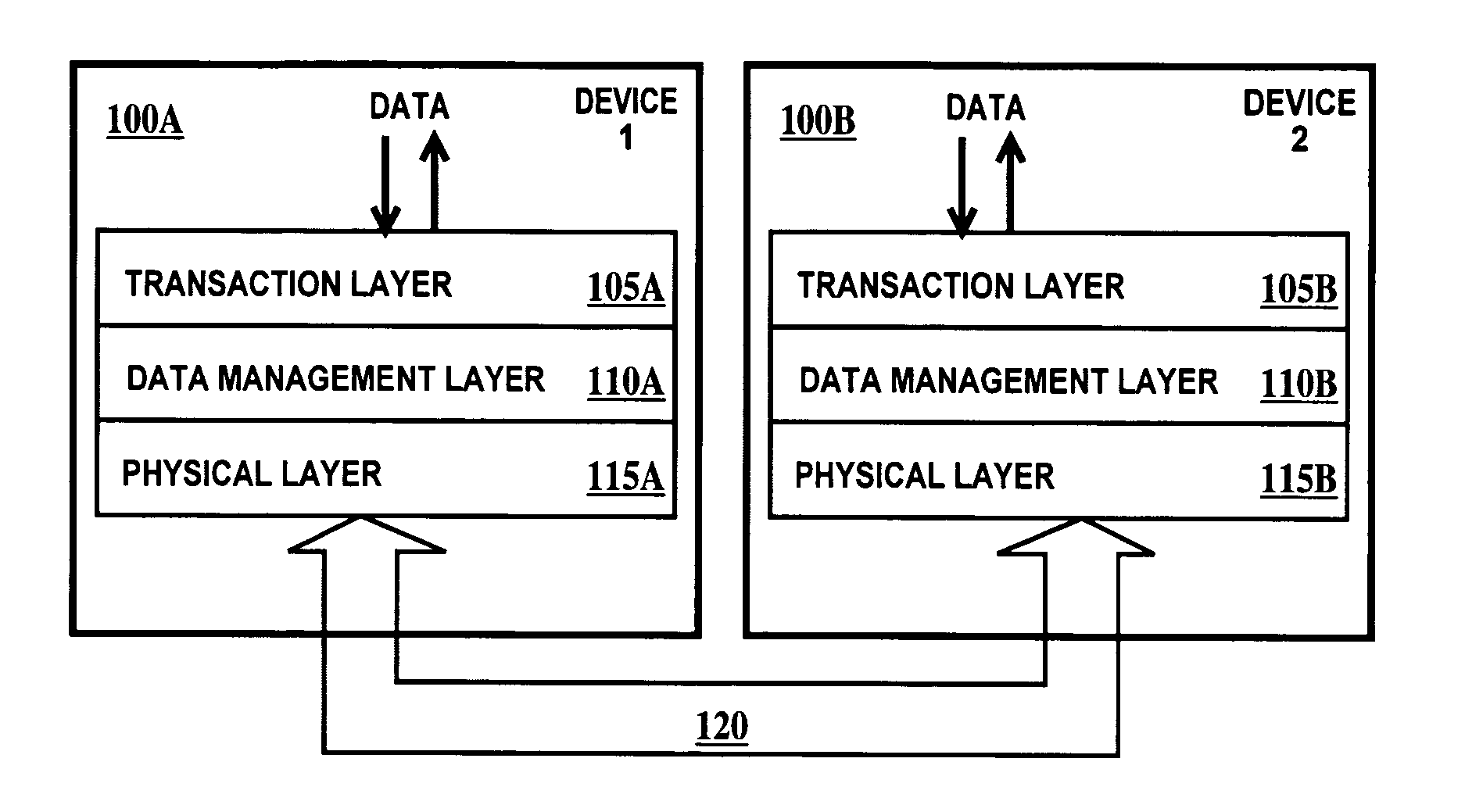
[0016] In describing layered bus protocol systems, different names for the same layer may be used. There are three layers of concern for the present invention. The first layer is the physical layer (also called the physical layer or layer 1 in the International Organization for Standardization (OSI) model). An example of a physical layer protocol is the well-known RS-232. The second layer is the data management layer (also called the link layer or the data link layer or layer 2 in the OSI model). The third layer is the transaction layer (also called the protocol layer or the network layer or layer 3 in the OSI model). Transaction layer protocols are used in controller area network (CAN) bus, asynchronous transfer mode (ATM), and high-level data link control (HDLC). The terms transaction layer, data management layer and physical layer will be used in describing the present invention, but it should be understood that the equivalent terms defined supra may be substituted.

[0017]FIG. 1 ...


PUM


Abstract

A data management layer of a layered protocol system and a method of transmitting data. The data management layer including: a cyclic redundancy check generator connected to a retry buffer through a multiplexer; a sequence number generator connected to the retry buffer through the multiplexer; means for generating a sequence number cyclic redundancy check remainder connected to preset inputs of a cyclic redundancy check remainder latch of the cyclic redundancy check generator; an input data bus connected directly to the cyclic redundancy check generator and connected to the retry buffer through the multiplexer; and an output data bus directly connected to the retry buffer.

Description

FIELD OF THE INVENTION [0001] The present invention relates to the field of data transmission in a computer network; more specifically, it relates to a method and an apparatus for efficient operation of a layered bus protocol system. BACKGROUND OF THE INVENTION [0002] A computer network includes two or more computers or other communication devices that are connected with one another so that each computer or device can send and receive information in data packet format from the others. In addition to providing physical connections between computers or devices in the network, a computer network provides a data transmission architecture. Logically, the data transmission architecture can be divided into layers in a layered protocol system, each layer providing a different function. Generally one layer is responsible for adding data checking to data packets so that errors in transmission can be caught and corrected by a retransmission of the data packet. [0003] Conventional methods requi...

Claims


Application Information

Patent Timeline
IPC IPC(8): H03M13/00
CPCH03M13/09
Inventor AMBILKAR, SHRIDHAR N.KURUP, GIRISH G.MISRA, ASHUTOSH
Owner IBM CORP
Why Eureka
Try Eureka