Filter element

a filter element and filter element technology, applied in the field of filter element, can solve the problems of often insufficient space for a conventional rectangular cartridge, and achieve the effects of reliable sealing, stabilizing properties, and reliable sealing

Active Publication Date: 2007-01-11
MANN HUMMEL GMBH
View PDF15 Cites 57 Cited by
  • Summary
  • Abstract
  • Description
  • Claims
  • Application Information

AI Technical Summary

Benefits of technology

[0009] A substantial advantage of the invention is that the filter element has an oval contour. This makes it possible to use installation spaces that are relatively low in height. To obtain such an oval contour of the filter medium, the filter medium is beveled, i.e., a filter medium is created whose shape is optimally adapted to the oval contour. The junction between the filter medium and the corresponding opening, which is to be covered by the filter element, is provided by a polyurethane foam frame having a sealing edge.
[0010] In accordance with one embodiment of the invention, the folds of the filter medium are bonded together along the outer faces to create an effective lateral seal. These outer faces are partly or completely embedded in the polyurethane foam. To reinforce the filter element, the folds may advantageously be provided with reinforcement strips along their peaks. These reinforcement strips comprise, for example, beads of hot melt adhesive or some other stabilizing material.
[0011] In a further refinement, a groove o

Problems solved by technology

The space is often insufficient for a conventional rectangular cartridge, so tha

Method used


Image

  • Filter element
  • Filter element
  • Filter element

Examples


Embodiment Construction

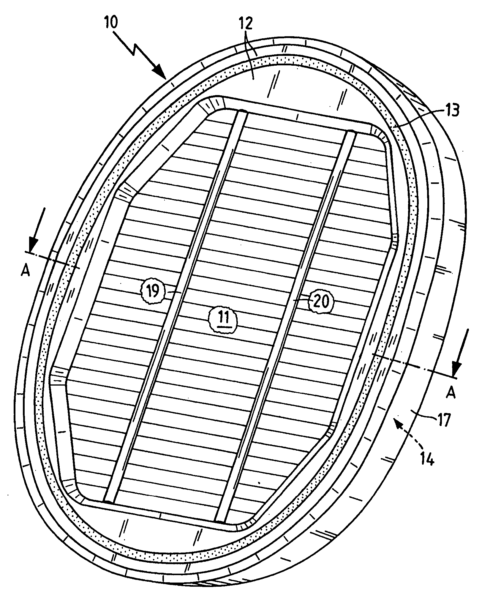
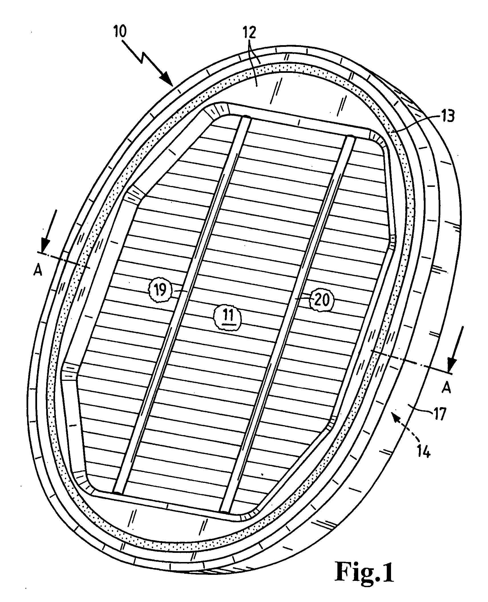
[0017]FIG. 1 shows a filter element 10 in the form of a secondary element for a filter system in the intake tract of an internal combustion engine. It comprises a zig-zag pleated, plate-like or flat filter medium 11 having a substantially rectangular shape. In the region of the curvatures, the filter medium is cut diagonally along the end faces to adapt it to the curve of the oval filter element 10.

[0018] The seal of the entire element is provided by a polyurethane foam frame 12, which has a circumferential groove 13. The passage for the air to be filtered has a maximum effective filter surface with a minimum of waste of filter medium. The polyurethane foam frame 12 is supported by a support frame 14, which is made of a thermoplastic material, e.g. polyamide or polypropylene.

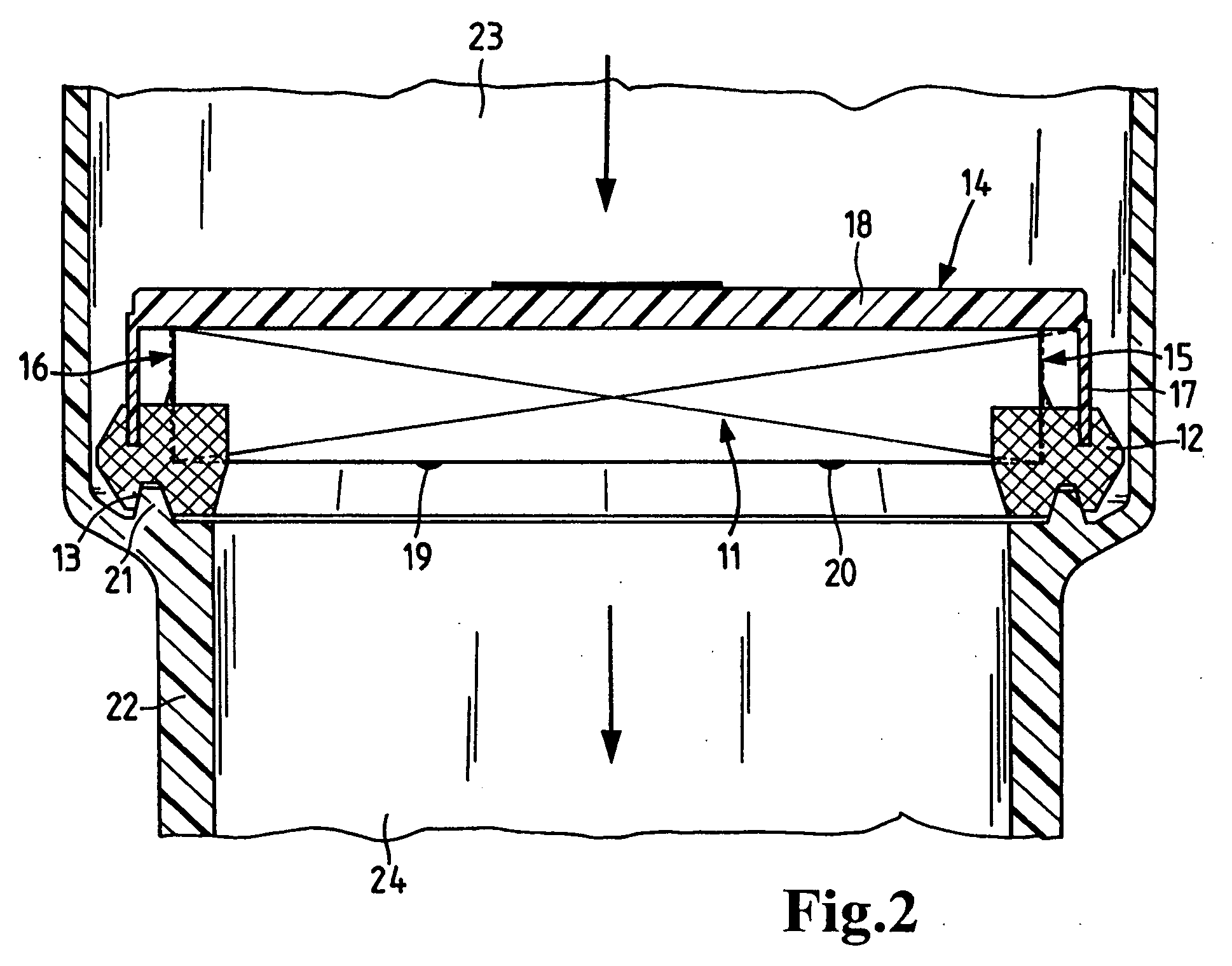
[0019]FIG. 2 is a sectional view of the parts depicted in FIG. 1 in which like parts are identified by the same reference numerals. The filter medium 11 is sealed along the face edges 15, 16 by an adhesive lay...


PUM


Abstract

A filter element, particularly a secondary element for a filter system in the intake tract of an internal combustion engine, which filter element includes a zig-zag pleated filter medium surrounded by a circumferential frame of polyurethane foam. The frame has a substantially oval contour and is insertable into an oval opening. To reproduce the oval contour, the plate-like medium has beveled lateral regions, such that a maximum effective filter surface is obtained with a minimum amount of waste. A circumferential groove or a circumferential web is provided in the frame to seal the polyurethane foam frame to the opening.

Description

BACKGROUND OF THE INVENTION [0001] The present invention relates to a filter element, particularly a secondary element for a filter system in the intake tract of an internal combustion engine, comprising a zig-zag pleated filter medium, which is surrounded by a circumferential frame of polyurethane foam. [0002] German patent no. DE 12 99 534 discloses a filter insert made of a folded filter material. This filter insert is provided with an adhesive mass, which is bonded to the filter material and extends transversely of the fold edges. This adhesive is used as a spacer. [0003] Conventional filters of this type for motor vehicle engines also use an adhesive mass or adhesive beads as spacers. Such adhesive beads are at the same time applied continuously along the sides of the filter material during manufacture. In zig-zag pleated filter materials, these adhesive beads serve as a lateral seal of the filter insert. [0004] With continued advances in automotive engineering and the developm...

Claims


Application Information

Patent Timeline
IPC IPC(8): B01D46/00
CPCB01D46/10B01D46/523B01D2279/60B01D2275/208B01D2271/022Y10S55/31
Inventor RUHLAND, KLAUS-DIETERKOPEC, EDVARD
Owner MANN HUMMEL GMBH
Why Eureka
Try Eureka