
Bump for overhang device

a technology of overhanging device and overhanging part, which is applied in the direction of semiconductor device, semiconductor/solid-state device details, electrical apparatus, etc., can solve the problems of overhanging part of the upper package cracking or breaking, upper package “tilt”, and unacceptable bonding at the die pad, so as to prevent mechanical failure (cracking or breaking) or tilting

Inactive Publication Date: 2007-01-04
STATS CHIPPAC LTD
View PDF13 Cites 49 Cited by
  • Summary
  • Abstract
  • Description
  • Claims
  • Application Information

AI Technical Summary

Benefits of technology

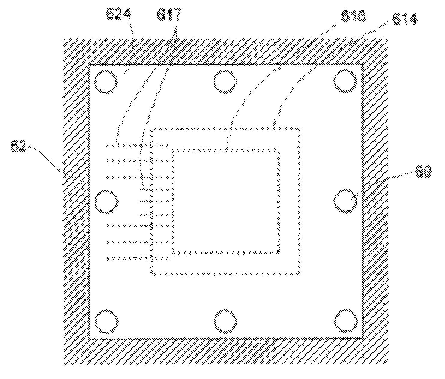
[0012] This invention is directed to providing support for a die or a package that overhangs a package substrate, and thereby preventing mechanical failure (cracking or breaking) or tilt. The overhanging feature (die or package) is stacked upon one or more of a die or a package or a spacer, and has a portion that overhangs the surface of the substrate on which the stacked features are mounted. According to the invention, discrete bumps made of a polymer (such as an electrically nonconductive epoxy) or a conductive material (such as an electrically conductive material) are interposed between the upper surface of the substrate and the lower surface of the overhanging part of the die or package. The bumps are dimensioned to provide a clearance between the upper surface of the “bottom” substrate and the under surface of the second die or “top” substrate.

Problems solved by technology

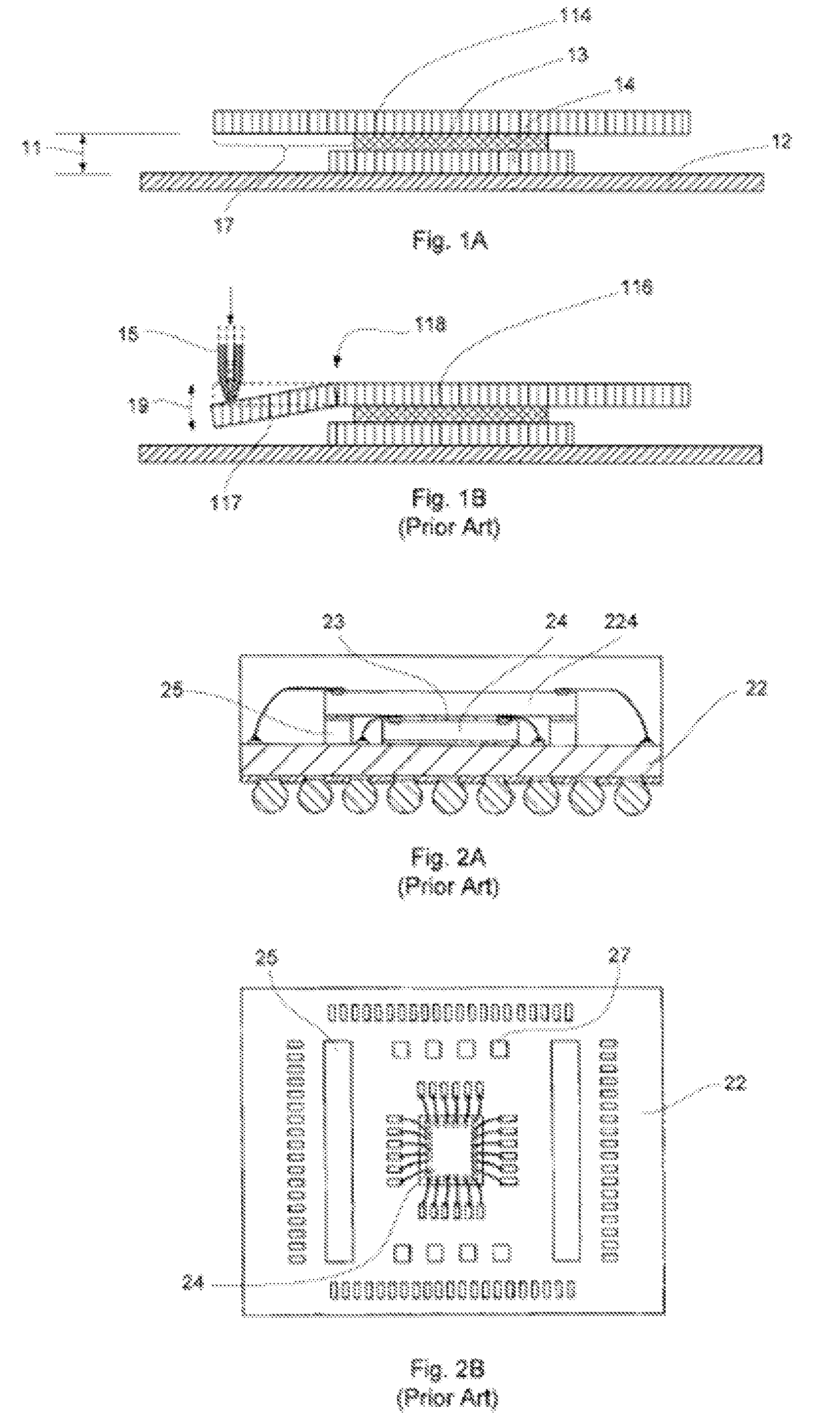
Or, where the die is very thin and the overhang is extensive, the overhanging portion may not crack or break, but may flex excessively during the wire bonding procedure, resulting in unacceptable bonds at the die pads.
The overhanging part of the upper package may crack or break or, as may be more likely, the upper package may “tilt” when the overhanging part is loaded.
Solutions to these problems have been long sought but prior developments have not taught or suggested any solutions and, thus, solutions to these problems have long eluded those skilled in the art.

Method used


Image

  • Bump for overhang device
  • Bump for overhang device
  • Bump for overhang device

Examples


Embodiment Construction

[0049] In the following description, numerous specific details are given to provide a thorough understanding of the invention. However, it will be apparent that the invention may be practiced without these specific details. In order to avoid obscuring the present invention, some well-known system configurations, and process steps are not disclosed in detail. Likewise, the drawings showing embodiments of the apparatus are semi-diagrammatic and not to scale and, particularly, some of the dimensions are for the clarity of presentation and are shown greatly exaggerated in the figures. In addition, where multiple embodiments are disclosed and described having some features in common, for clarity and ease of illustration, description, and comprehension thereof, similar and like features one to another will ordinarily be described with like reference numerals.

[0050] The term “horizontal” as used herein is defined as a plane parallel to the conventional integrated circuit surface, regardle...


PUM


Abstract

A semiconductor package system is provided including forming a support platform, mounting a first device over the support platform, forming a bump on the support platform, and mounting a second device on the first device and the bump.

Description

CROSS-REFERENCE TO RELATED APPLICATION [0001] This application is a continuation-in-part of co-pending U.S. patent application Ser. No. 11 / 420,853 filed May 30, 2006, by Hun Teak Lee, Jong Kook Kim, ChulSik Kim, and Ki Youn Jang, which is a Non Provisional of U.S. Provisional patent application Ser. No. 60 / 686,116 filed May 31, 2005. [0002] This application also claims the benefit of U.S. Provisional patent application Ser. No. 60 / 596,103 filed Aug. 31, 2005, by Ki Youn Jang, Keon Teak Kang, and Hyung Jun Jeon.TECHNICAL FIELD [0003] The present invention relates generally to semiconductor packages and more particularly to molded semiconductor packages. BACKGROUND ART [0004] A conventional chip package consists of a semiconductor die affixed to a surface of a substrate and electrically interconnected to bonding pads on the substrate surface. The opposite surface of the substrate has an array of solder balls for electrical connection to, for example, a motherboard. The substrate inclu...

Claims


Application Information

Patent Timeline
Patent Type & Authority Applications(United States)
IPC IPC(8): H01L23/34
CPCH01L23/562H01L24/10H01L24/81H01L24/85H01L25/0657H01L2224/13099H01L2224/16145H01L2224/32014H01L2224/32145H01L2224/48091H01L2224/48227H01L2224/81801H01L2224/83856H01L2224/92247H01L2225/0651H01L2225/06517H01L2225/06555H01L2225/06562H01L2225/06575H01L2924/14H01L2924/15311H01L2924/3025H01L24/48H01L2924/00013H01L24/83H01L2224/85H01L24/78H01L2224/32225H01L2224/73265H01L2224/78301H01L2224/131H01L2924/07802H01L24/13H01L2924/00014H01L2924/3512H01L2924/00H01L2924/014H01L24/49H01L2224/05554H01L2224/05573H01L2224/13H01L2224/49175H01L2924/10161H01L2924/181H01L2924/00012H01L2224/45099H01L2224/45015H01L2924/207
Inventor LEE, HUN TEAKKIM, JONG KOOKKIM, CHULSIKJANG, KI YOUNKANG, KEON TEAKJEON, HYUNG JUN
Owner STATS CHIPPAC LTD
Learn More