
Method and System for controlling coal flow

a technology of flow control and coal flow, applied in the direction of combustion control, solid fuel combustion, lighting and heating apparatus, etc., can solve the problems of reduced combustion efficiency, physical differences, and poor balance of pulverized coal distribution between burner pipes

Inactive Publication Date: 2007-01-04
GENERAL ELECTRIC CO
View PDF22 Cites 19 Cited by
  • Summary
  • Abstract
  • Description
  • Claims
  • Application Information

AI Technical Summary

Problems solved by technology

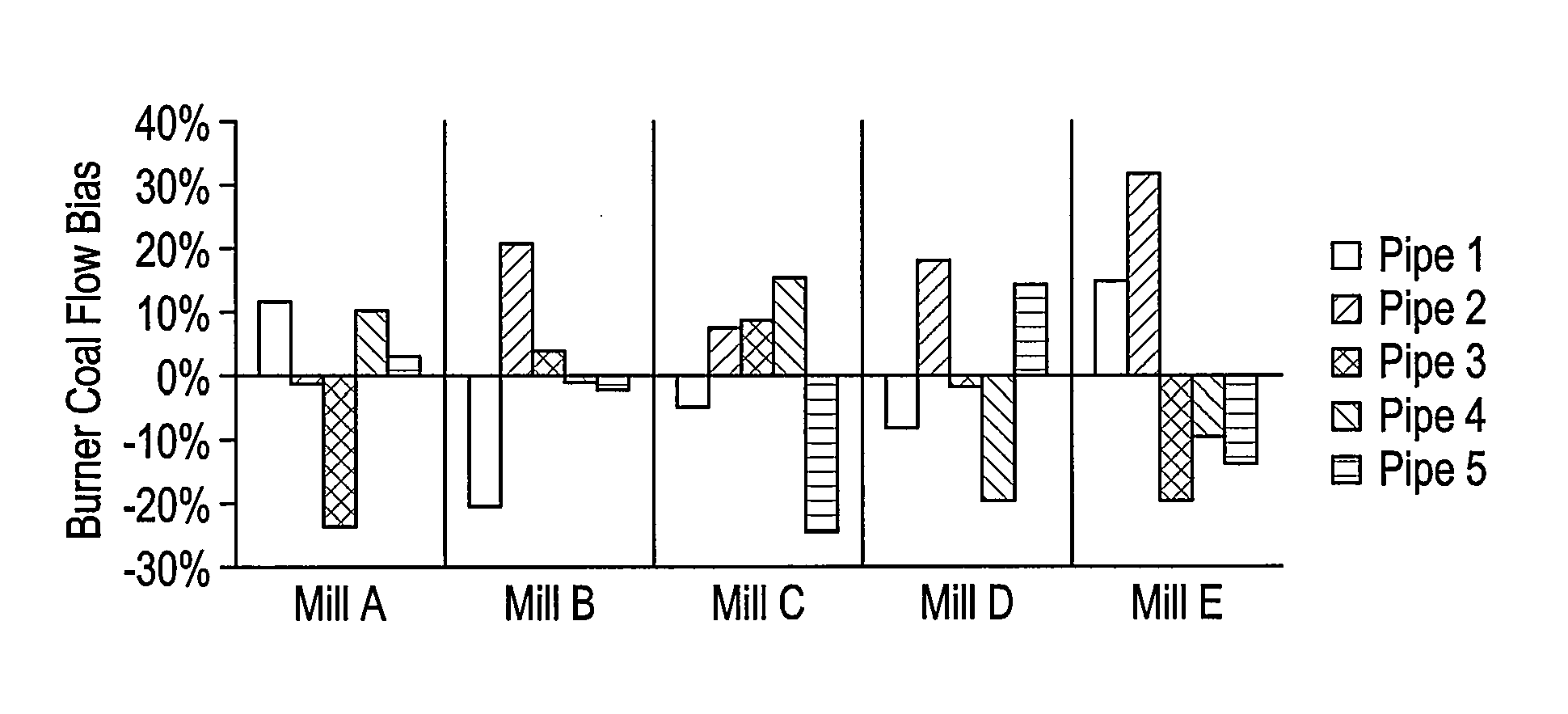
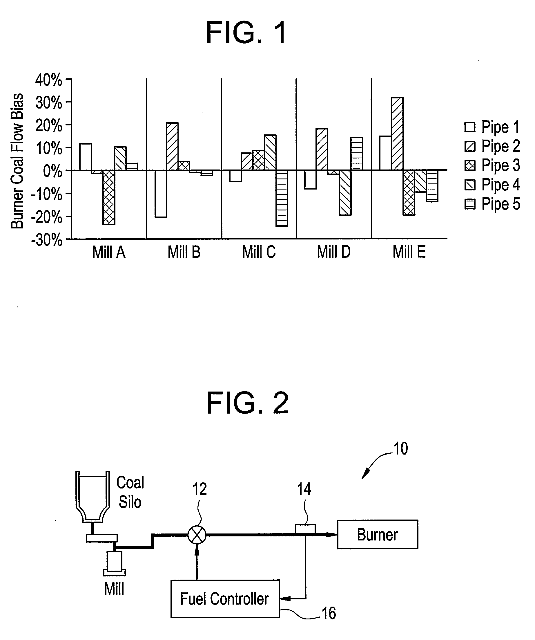
Poor balance of pulverized coal distribution between burner pipes is commonly experienced in boilers.
This imbalance results from, inter alia, system resistance of each individual fuel conduit, physical differences inside the pulverizer, and coal fineness.
Unbalanced and generally random varying distribution of coal among the burner pipes adversely affects unit performance and leads to decreased combustion efficiency, increased unburned carbon in fly ash, increased potential for fuel line plugging and burner damage, increased potential for furnace slagging, and irregular heat release within the combustion chamber.

Method used


Image

  • Method and System for controlling coal flow
  • Method and System for controlling coal flow
  • Method and System for controlling coal flow

Examples


Embodiment Construction

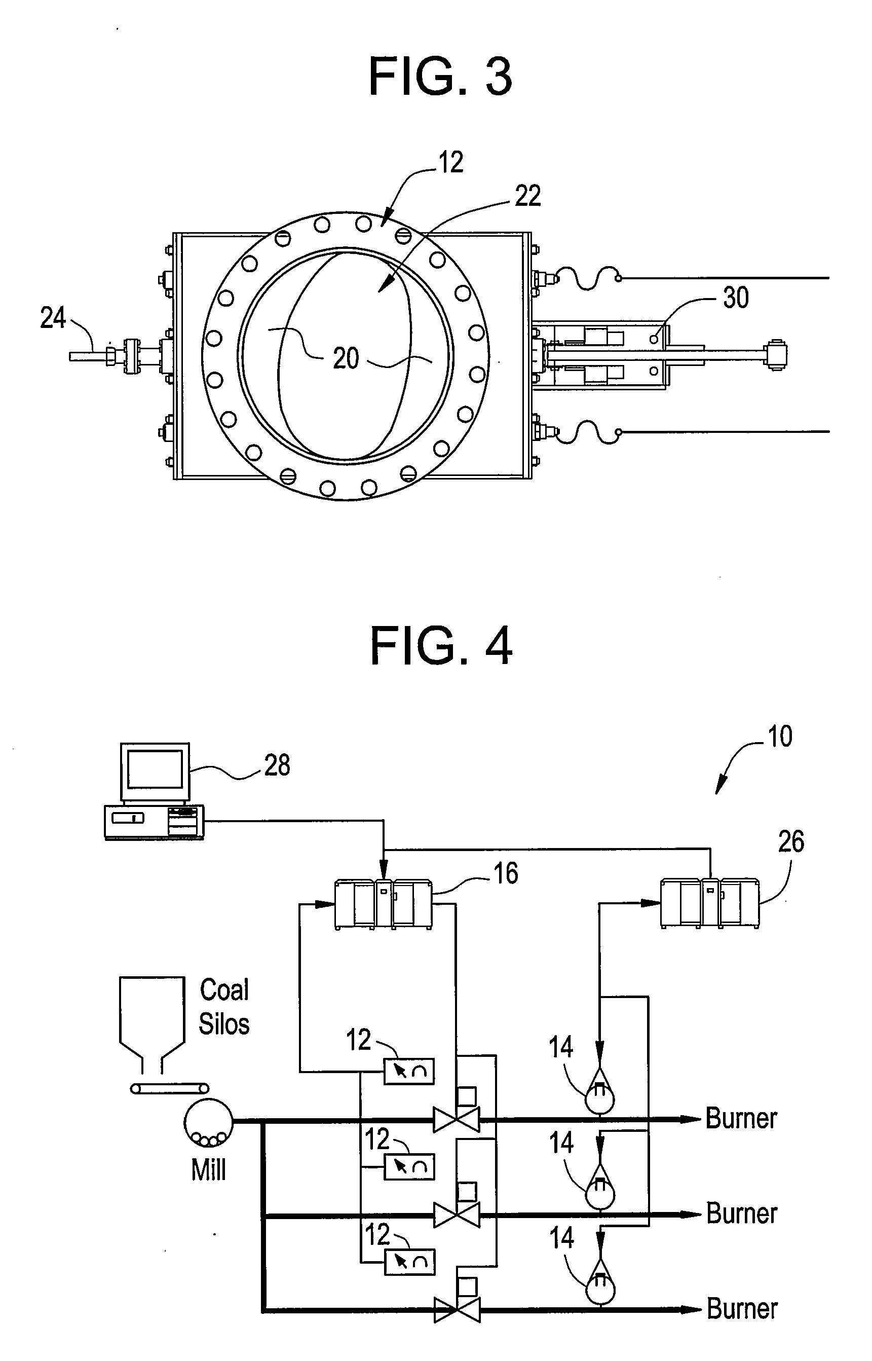
[0019] In coal fired boilers, balanced coal flow among burners is traditionally an important factor for combustion optimization. In order to effectively optimize furnace combustion performance, coal flow to each individual burner must be closely controlled. Coal flow control can be accomplished automatically and continuously through the use of a coal flow control system. Referring to FIG. 2, an exemplary embodiment of the coal flow control system is shown generally at 10. A coal flow sensor 14 measures the coal flow in a burner pipe and communicates a coal flow signal, indicative of coal flow in the burner pipe, to a fuel trim controller 16. A coal flow damper 12 controls the coal flow in the burner pipe and receives command signals from the fuel trim controller 16. The coal flow damper 12 is discussed in more detail hereinafter with reference to FIG. 3. The fuel trim controller 16 receives the coal flow signal from the coal flow sensor 14 and input signals from a controller, indica...


PUM


Abstract

A system for controlling coal flow in a coal-fired boiler including: a coal flow damper in operable communication with a burner pipe; a coal flow sensor in operable communication with the burner pipe which generates a coal flow signal; and a fuel trim controller in operable communication with the coal flow damper, the fuel trim controller controlling the coal flow damper responsive to the coal flow signal.

Description

BACKGROUND [0001] The present disclosure relates generally to a method and system for controlling coal flow, and more particularly to controlling the coal flow to the burners in a coal fired boiler in order to optimize boiler operations. [0002] Coal fired boilers utilize pulverizers to grind coal to a desired fineness so that it may be used as fuel for the boilers. Typically, raw coal is fed through a central coal inlet at a top of the pulverizer and falls by gravity to a grinding area. Once pulverized, the coal is transported upwards, using air as the transport medium. The pulverized coal passes through classifier vanes within the pulverizer. These classifier vanes may vary in structure, but are intended to establish a swirling flow within a “rejects” cone to prevent coarse coal particles from flowing into a discharge turret of the pulverizer. The centrifugal force set up in the “rejects” cone forces coarse coal particles to drop back down into the grinding area until the desired f...

Claims


Application Information

Patent Timeline
Patent Type & Authority Applications(United States)
IPC IPC(8): F23B90/00F23N5/18
CPCF23K3/00F23K2203/104F23K2203/105F23N1/002F23N2041/10F23N2035/12F23N2037/02F23N2039/02F23N5/184F23N2237/02F23N2239/02F23N2241/10F23N2235/12
Inventor WIDMER, NEIL COLINGAUTHIER, PHILIPPE
Owner GENERAL ELECTRIC CO
Learn More