
Method and system for defining media objects for computer network monitoring

Active Publication Date: 2006-12-28
ARB INTPROP HLDG HK
View PDF4 Cites 31 Cited by
  • Summary
  • Abstract
  • Description
  • Claims
  • Application Information

AI Technical Summary

Benefits of technology

[0006] It is an object of the present invention to provide users with the ability to arbitrarily create media objects, e.g., images, representative of the enterprise-wide environment from servers to all worldwide devices.
[0007] It is an object of the present invention to permit users to add their own arbitrarily defined and selected media objects very efficiently without much time and effort.

Problems solved by technology

Today, there is no useful means to arbitrarily assign a graphic or picture, for example that represents a networked asset, such as a network node, when monitoring a computer network.
However, the user of a monitoring application has no means to define a representation, which is tailored and user-defined.

Method used


Image

  • Method and system for defining media objects for computer network monitoring
  • Method and system for defining media objects for computer network monitoring
  • Method and system for defining media objects for computer network monitoring

Examples


example 1

[0042] Example 1

       0” / >    0” / >  0” / >    0” / >  255, 0” / >  0” / >                                                                      0” / >  0” / >                          0” / >  255, 0” / >                    Main Servers” type=“monitoring group” / >  Server Pools” type=“monitoring group” / >     

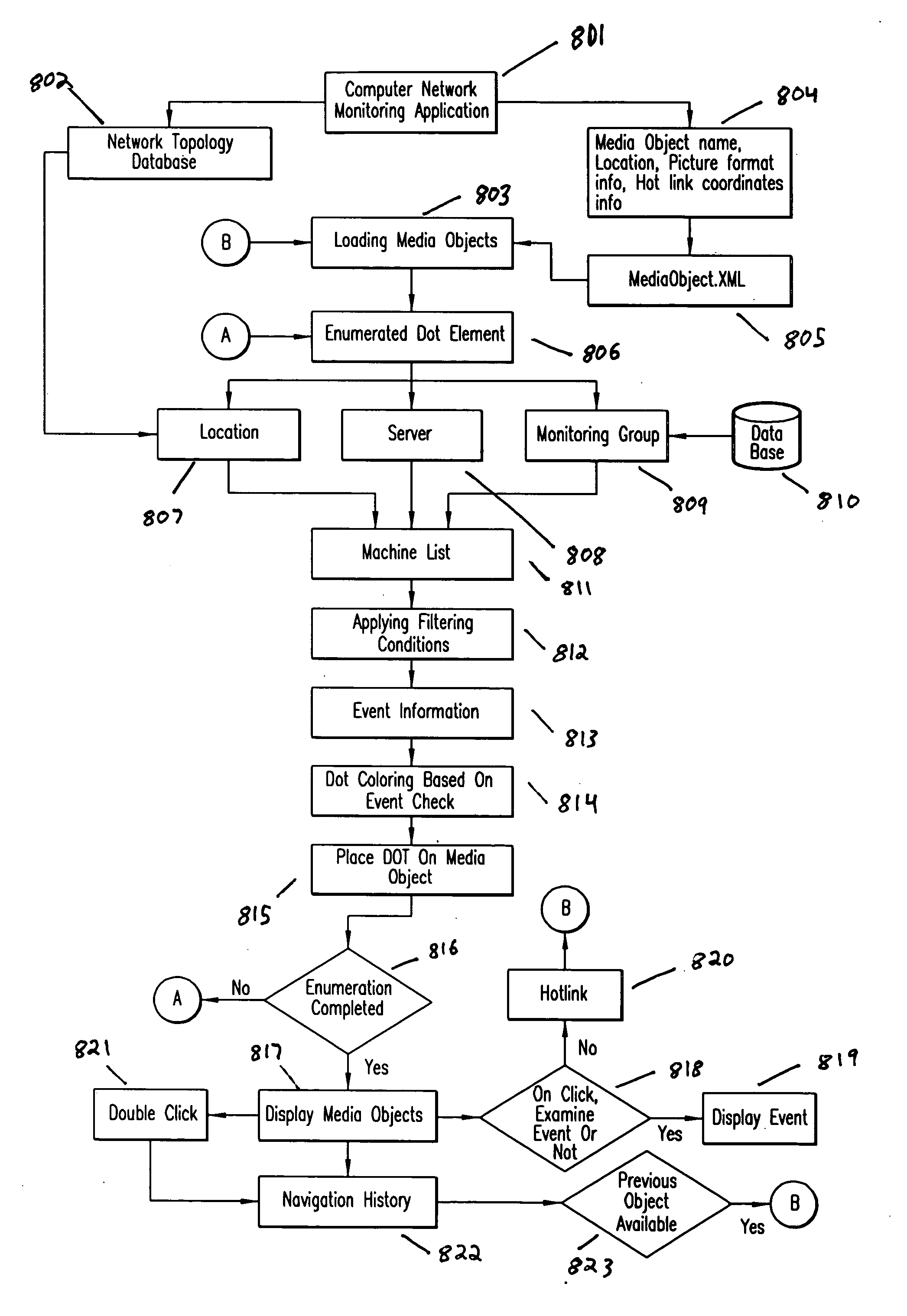
[0043] According to the present invention, the XML file can be parsed using a conventional XML parser library application.

[0044] The present invention stores a location for each network group in a network topology database 802, e.g., network.xml as defined below. However, it should be noted that any conventional database structure can be utilized, e.g., SQL database, for example. In this embodiment, all the server / devices in the same group share the same location. Following is an example of an inventory resource tool monitor:

example 2

[0045] Example 2

 gateway=“T1” firewall=“yes”>  ip=“65.217.205.221” / >  gateway=“T1” firewall=“yes”>  ip=“65.217.205.222” / >  gateway=“T1” firewall=“yes”>  ip=“65.220.118.34” / >  gateway=“T1” firewall=“yes”>  ip=“69.37.81.83” / >  gateway=“T1” firewall=“yes”>  ip=“65.220.118.36” / > 

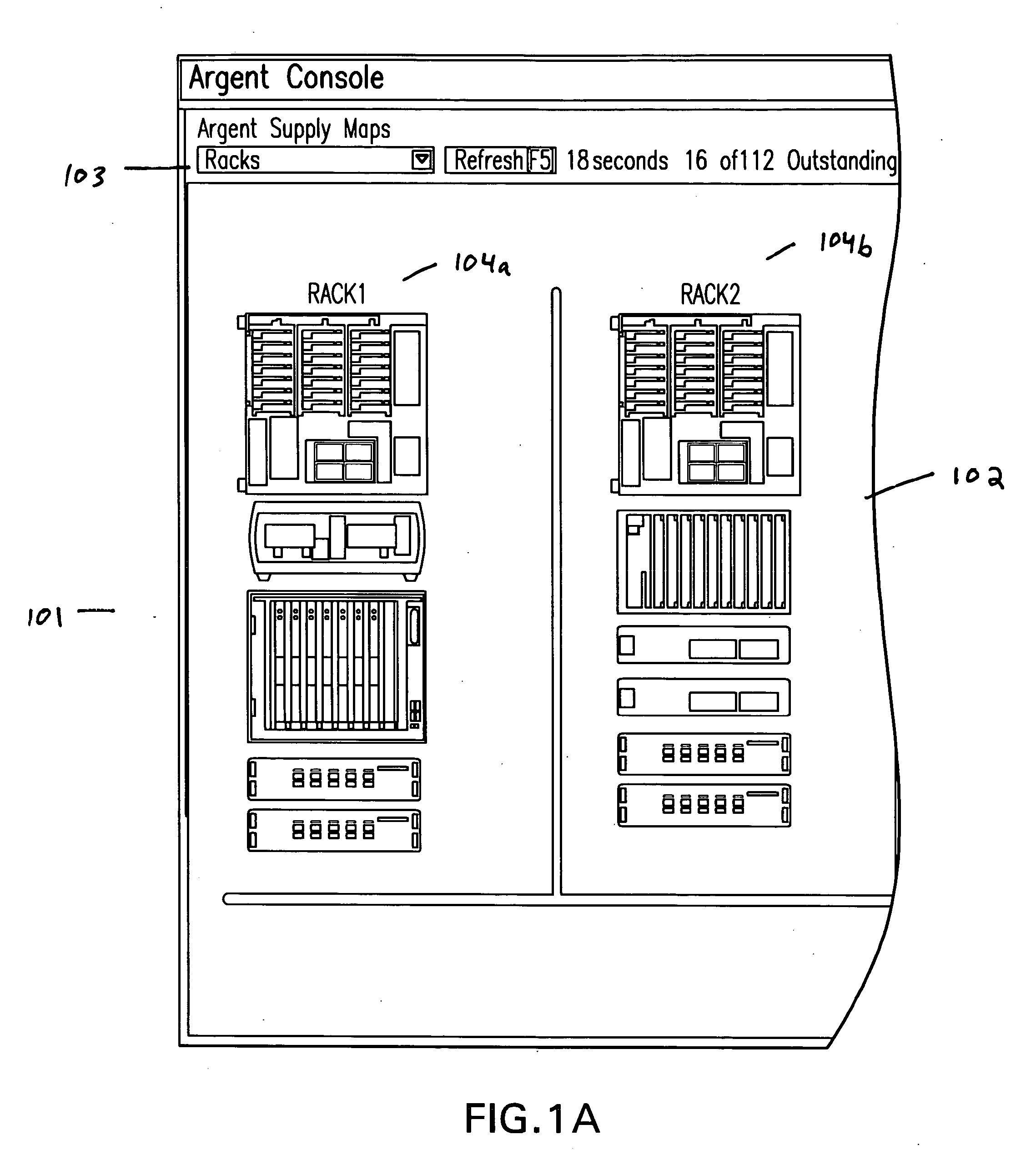
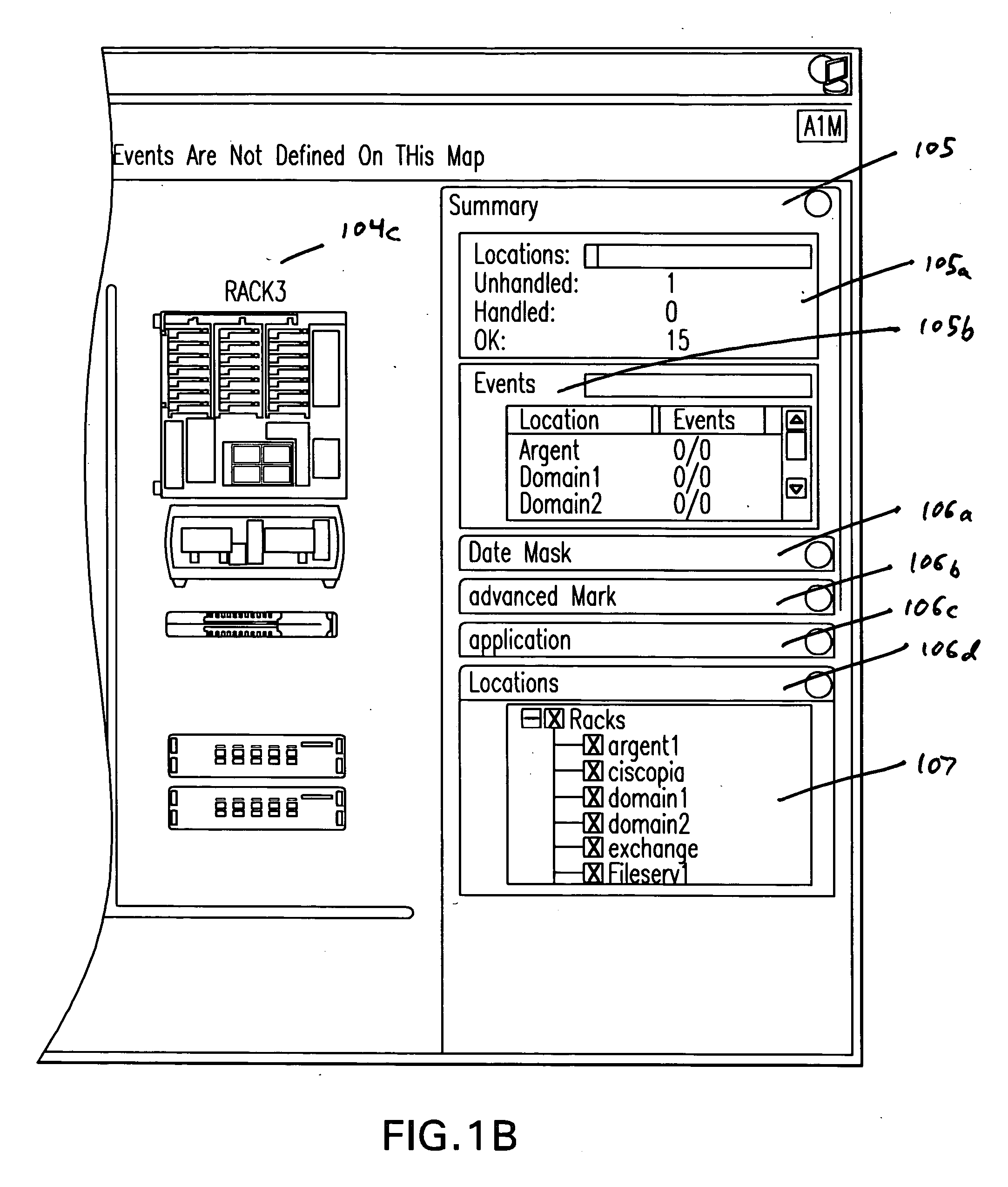
[0046] The present invention permits the displaying of user created, defined and selected media objects as images, irrespective of initial or intermediate format, e.g., JPEQ, BMP, etc., as a background screen scene of a user interface for computer network resource monitoring. The image is displayed proportionally as a media object to fit the screen resolution of a user interface. The media object can be displayed in a custom static control, among other conventional design and display manners. A conventional image library can also be used to load media object in JPEG, BMP and / or other image formats. In an alternate embodiment, drawing an image, e.g., software drawing application, is used to create the media objec...


PUM


Abstract

Method and system for defining media objects, such as images and graphics, to represent computer networked resources and assets, along with their associated events, while monitoring the same in a real-time environment is disclosed.

Description

CLAIM OF PRIORITY UNDER 35 U.S.C. §119 [0001] The present Application for Patent claims priority to Provisional Application No. 60 / 693,772 entitled “Method and System for Defining Media Objects for Computer Network Monitoring” filed Jun. 27, 2005, and assigned to the assignee hereof and hereby expressly incorporated by reference herein.BACKGROUND [0002] The described embodiments generally relate to monitoring computer networks. More particularly, the described embodiments relate to a method and system for arbitrarily defining media objects to represent computer networked resources and assets, along with their associated events, while monitoring the same. [0003] Today, there is no useful means to arbitrarily assign a graphic or picture, for example that represents a networked asset, such as a network node, when monitoring a computer network. As of now, a representation is predetermined and pre-selected to represent the asset, such as a hyperbolic computer network monitoring map, in c...

Claims


Application Information

Patent Timeline
IPC IPC(8): G06F15/173G06F17/00
CPCG06F11/327H04L63/02G06F11/3495
Inventor BLENCOWE, ANDREW
Owner ARB INTPROP HLDG HK
Learn More