
Robotic floor care appliance with improved remote management

Inactive Publication Date: 2006-12-28
POGODIN PAVEL
View PDF3 Cites 184 Cited by
  • Summary
  • Abstract
  • Description
  • Claims
  • Application Information

AI Technical Summary

Benefits of technology

[0007] The present invention is directed to methods and systems that substantially obviate one or more of the

Problems solved by technology

Both of the above methods suffer from two major flaws.
In both cases, there is no facility provided for scheduling the operation of the appliance at a future time.
Furthermore, the specialized remote controls of the existing robotic appliances are complex and difficult to use.
Thus, the existing methods for controlling robotic floor care appliances are deficient in their ability to provide for an easy and efficient remote management of the robotic device.
The existing techniques also do not provide for ability to easily schedule future floor maintenance operations to be performed by the robotic appliance in a periodic and non-periodic manner.

Method used


Image

  • Robotic floor care appliance with improved remote management
  • Robotic floor care appliance with improved remote management
  • Robotic floor care appliance with improved remote management

Examples


exemplary embodiment 500

[0056]FIG. 5 illustrates an exemplary embodiment 500 of a floor care scheduling input form in accordance with the inventive concept. The columns of the form 500 in FIG. 5 represent weekdays, while the rows correspond to the time of day. The user schedules the floor care operation for a particular time of a particular day by selecting a box at the intersection of an appropriate row and column in the form 500. In one implementation, the scheduling form covers one week and the floor care operation is conducted regularly thereafter according to the same schedule each week, until the schedule is subsequently adjusted.

exemplary embodiment 600

[0057]FIG. 6 illustrates an alternative exemplary embodiment 600 of a floor care scheduling input form in accordance with the inventive concept. In this embodiment, the user may specify the date, time and duration of the floor care operation, as well as the time period after which the floor care operation is repeated. For example, the user may specify that the floor care operation should take place weekly starting on a specific date and time. Alternatively, the user may schedule one-time cleaning without the repeat feature.

[0058] In an embodiment of the inventive appliance, when the amount of the floor care supplies in the appliance drops below a predetermined threshold value, when the internal dust / waste water container in the appliance becomes full, or when the appliance otherwise needs service, it may alert the user of the problem. This can be accomplished in a variety of ways. In one embodiment of the invention, the appliance, through the network 111, activates a software progra...


PUM


Abstract

A robotic floor care appliance with flexible web-enabled scheduling and status information / diagnostics systems. The robotic floor care appliance is supplied with a wireless network interface unit, which enables the appliance to establish network connections with remote network entities. The appliance may be provided with web and / or e-mail server(s) to enable the user to easily access the status / diagnostic information of the appliance and to furnish scheduling information to the appliance via various web-enabled protocols. The status / diagnostic information may be displayed to the user as a web page or sent to the user via e-mail. The scheduling information may be received from the user and transmitted to the appliance via HTTP protocol. The appliance may use web or e-mail connections to automatically notify the user of the status of the cleaning supplies, presence of malfunctions, if any, and the need for service. The appliance may also send the performance information to the manufacturer, which can be used to diagnose performance problems, create software patches, and to improve design of future products. Finally, the appliance may automatically download control software updates via a network connection.

Description

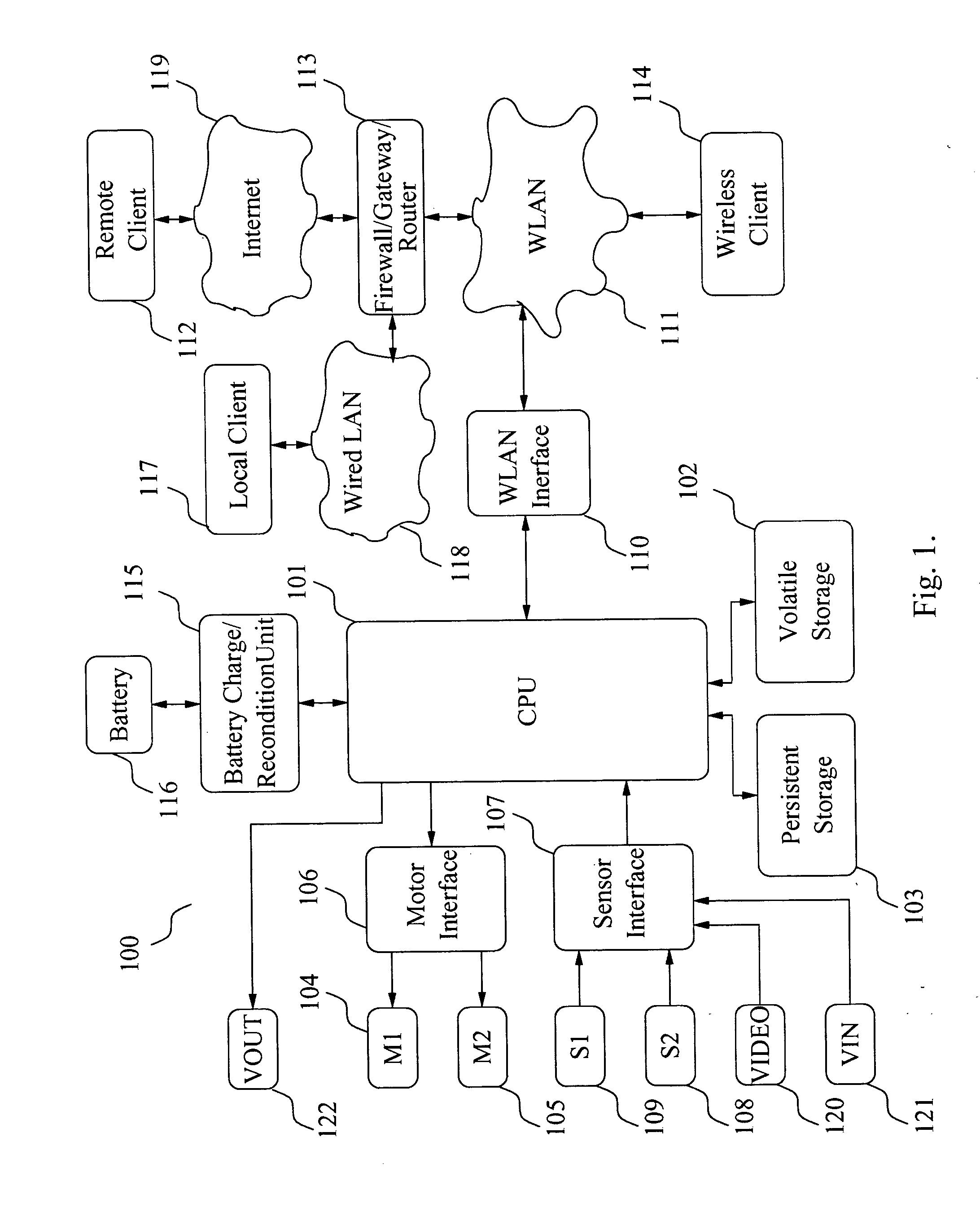
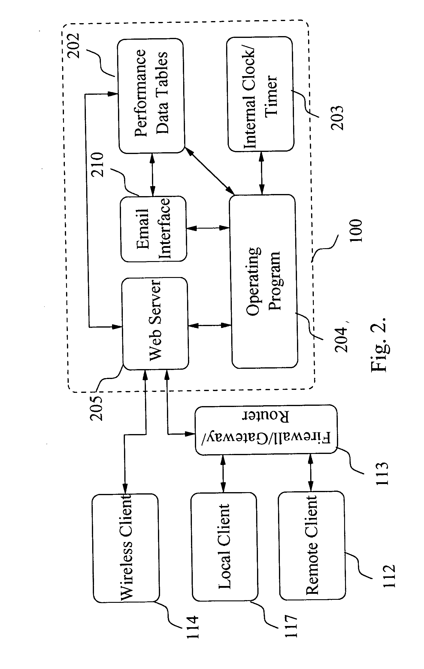
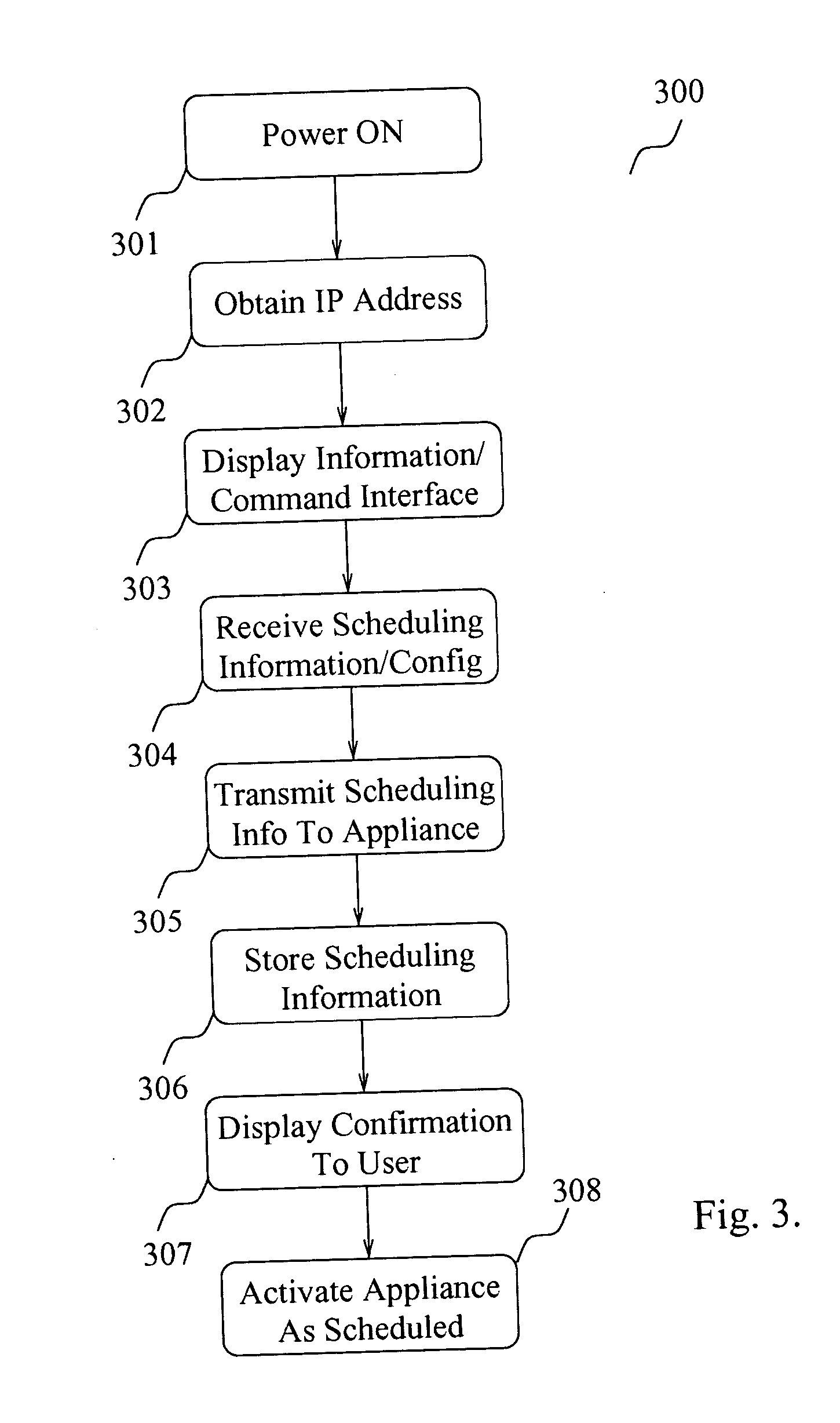
FIELD OF THE INVENTION [0001] The present invention generally relates to the robotic floor care appliances and more specifically to managing robotic floor care appliances in a remote manner. DESCRIPTION OF THE RELATED ART [0002] Several vendors offer robotic floor care appliances of varying types, including vacuum cleaners and liquid solution-based floor scrubbers. The aforementioned robotic floor care appliances will be referred to herein as such, and as “robotic appliances” or simply “appliances.” The robotic appliances perform the floor care operations with minimal human participation, autonomously guiding themselves along the floor surface. [0003] The operation of most robotic floor care appliance is controlled by one or more microprocessors, which send control commands to the drive unit of the appliance based on the readings from one or more of sensors installed in the appliance. The drive unit typically consists of a set of one or more electric motors. Another set of motors ma...

Claims


Application Information

Patent Timeline
IPC IPC(8): G06F19/00
CPCG05D1/0011G05D1/0225G05D1/0227H04L67/12G05D2201/0215A47L2201/04G05D1/0246
Inventor POGODIN, PAVEL
Owner POGODIN PAVEL
Learn More