
Touch sensing apparatus and method

Active Publication Date: 2014-06-26
LG DISPLAY CO LTD
View PDF13 Cites 38 Cited by
  • Summary
  • Abstract
  • Description
  • Claims
  • Application Information

AI Technical Summary

Benefits of technology

The invention provides a way to sensitively detect touch using a special technique that corrects for any differences in sensing between different parts of the touch device. This helps to ensure accurate detection of touch signals.

Problems solved by technology

However, a conventional touch controller has some problems in that it cannot correctly sense a touch signal since a signal to noise ratio (SNR) is low due to a noise component introduced into a readout signal through a touch sensor.
Data of a no-touch state of the touch sensor or a touchscreen has non-uniformity whereby the data varies according to a touch node, which is causes by manufacturing processes of the touchscreen and various non-uniformity such as non-uniformity of routing from a touch point to a sensor circuit.
However, the conventional touch sensing technology is vulnerable to noise.
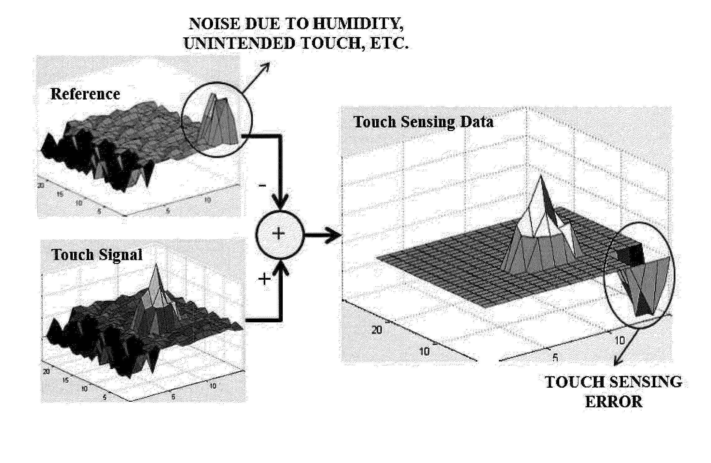
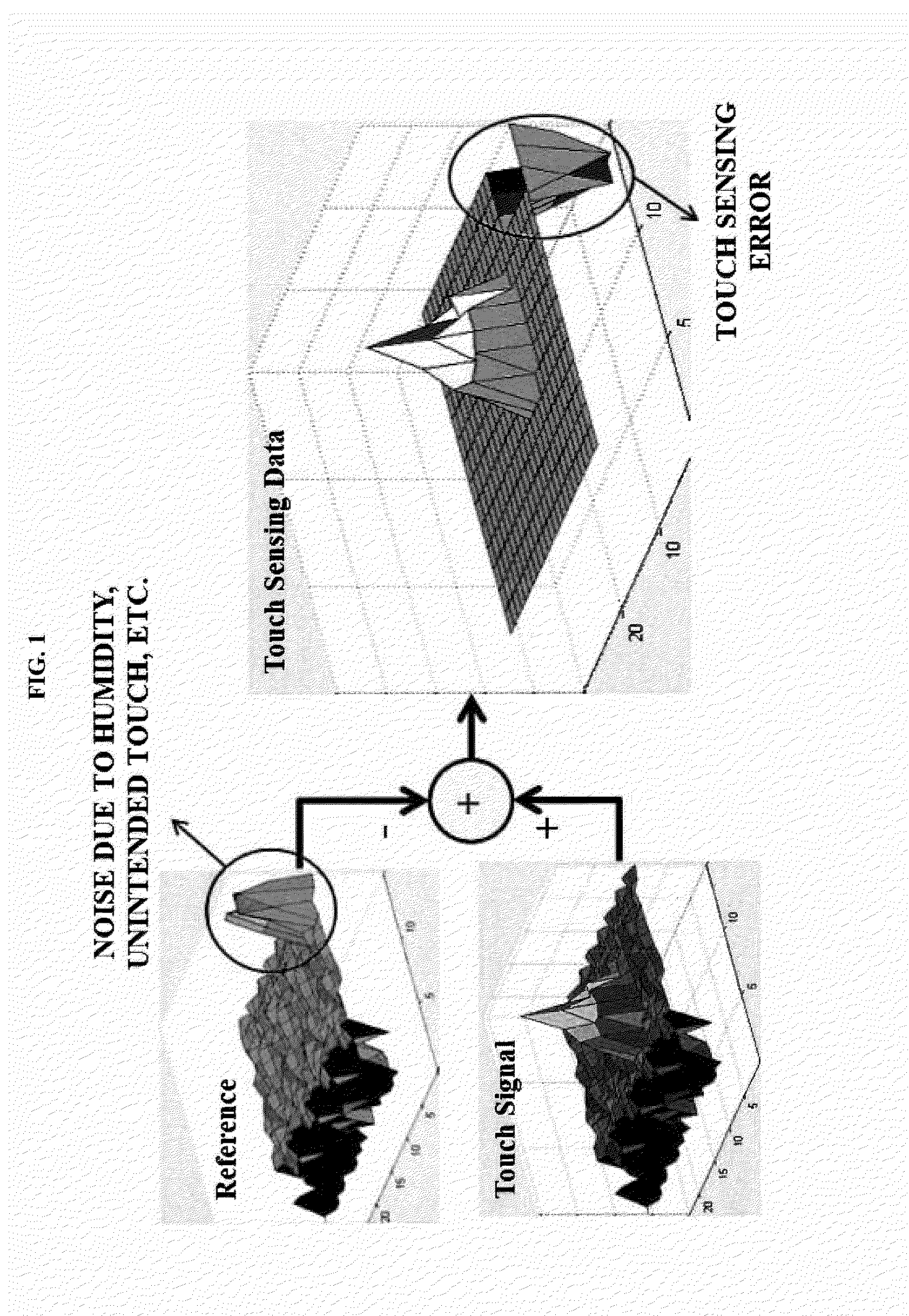
As shown in FIG. 1, in the conventional touch sensing technology, when artificial noise is introduced into the reference data in the no-touch state, a noise component is introduced into the touch sensing data corresponding to the difference value between the sensed touch signal and the reference data, resulting in touch sensing error.
In addition, in the conventional touch sensing technology, when an environment at a time that the reference data of the no-touch state is acquired and an environment at a time that an actual touch is performed become different from each other, for example, when although there is no noise during acquisition of the reference data, noise is generated during acquisition of touch sensing data in reality, touch sensing error occurs.

Method used


Image

  • Touch sensing apparatus and method
  • Touch sensing apparatus and method
  • Touch sensing apparatus and method

Examples


Embodiment Construction

[0035]Reference will now be made in detail to the preferred embodiments of the present invention, examples of which are illustrated in the accompanying drawings.

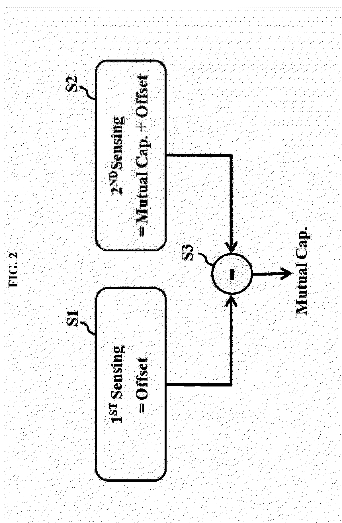
[0036]FIG. 2 is a schematic diagram for explaining a touch sensing method according to an embodiment of the present invention.

[0037]In the touch sensing method according to the present invention, a first sensing for sensing an offset component of each touch node and a second sensing for sensing a mutual capacitive component based on whether a touch is performed and the offset component are consecutively performed, and then, a differential operation is performed on a first sensing value from a second sensing value to acquire touch sensing data corresponding to a mutual capacitive component from which the offset component is removed.

[0038]In detail, in a first sensing step (S1), a driving pulse is not applied to a touch sensor, and a pure offset component excluding the mutual capacitive component is sensed and is output as a f...


PUM


Abstract

A touch sensing apparatus and method for correctly sensing a touch signal by removing an offset per touch node via differential sensing are discussed. The touch sensing method includes sensing a first sensing value including an offset component per touch node using a read out signal of a touch sensor, the touch sensor not being supplied with a driving pulse, in a first sensing period; sensing a second sensing value including the offset component of the touch node and a mutual capacitive component based on whether a touch is performed, using a read out signal of the touch sensor, the touch sensor being supplied with a driving pulse, in a second sensing period; and acquiring touch data from which the offset component is removed via a differential operation of the second sensing value and the first sensing value.

Description

[0001]This application claims the benefit of Korean Patent Application No. 10-2012-0152903, filed on Dec. 26, 2012, which is hereby incorporated by reference as if fully set forth herein.BACKGROUND OF THE INVENTION[0002]1. Field of the Invention[0003]The present invention relates to a touch sensing apparatus and method for correctly sensing a touch signal by removing an offset per touch node via differential sensing.[0004]2. Discussion of the Related Art[0005]Today, a touch sensor that can input information through a touch on a screen of various display apparatuses has been widely used as an information input device of a computer system. The touch sensor allows a user to move or select displayed information by simply touching the screen with a finger or a stylus, and thus, can be easily used by men and women of all ages.[0006]A touch sensor detects a touch and touch location generated on a display apparatus and outputs touch information. A computer system analyzes the touch informat...

Claims


Application Information

Patent Timeline
IPC IPC(8): G06F3/044
CPCG06F3/0412G06F3/04182G06F3/0446G06F3/0418G06F3/044G06F3/04166
Inventor PARK, DONG-JO
Owner LG DISPLAY CO LTD
Learn More