Rotation angle detection device and electric power steering apparatus employing the same

Inactive Publication Date: 2006-12-28
HONDA MOTOR CO LTD
View PDF7 Cites 36 Cited by
  • Summary
  • Abstract
  • Description
  • Claims
  • Application Information

AI Technical Summary

Benefits of technology

[0010] The objective of the present invention, therefore, is to provide a rotation angle detection device and an electric, power steering apparatus that employs this detection device wherein the detection device reduces the dependency of the abnormality determination operation on the intensity of a signal, and shortens the period of time required to determine whether an output abnormality has occurred.
[0021] According to this invention, a rotation angle detection device, which reduces dependence on the intensity of a signal and shortens the period required for the operation for determining whether an abnormality has occurred, and an electric power steering apparatus that employs this detection device can be provided.

Problems solved by technology

Thus, a predetermined detection margin is required, and an abnormality can not be detected unless the abnormal state continues for an extended period of time.
Further, when the detection method is used to calculate the sum of the squares, a reliable detection process can not be performed when the values of the sine wave signal and the cosine wave signal are not greatly changed.

Method used


Image

  • Rotation angle detection device and electric power steering apparatus employing the same
  • Rotation angle detection device and electric power steering apparatus employing the same
  • Rotation angle detection device and electric power steering apparatus employing the same

Examples


first embodiment

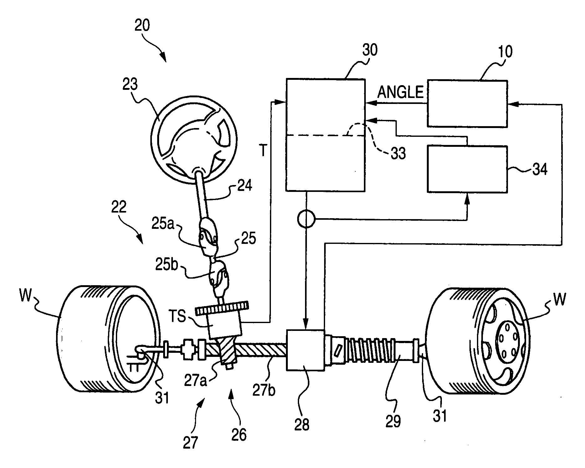
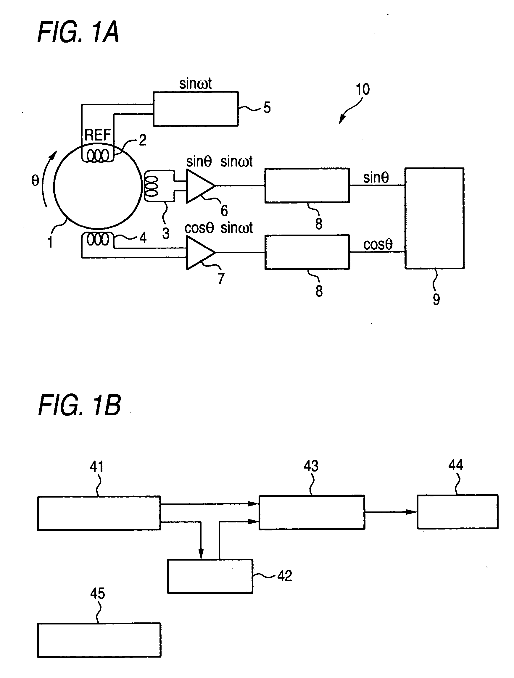
[0030] While referring to FIG. 1A, an explanation will be given for the hardware configuration of a resolver (a rotation angle detection device) 10 that detects the rotation angle of a motor employed to augment the force exerted by an electric power steering apparatus.

[0031] The resolver 10 includes, as its main components: a rotor 1 which interacts with the rotary shaft of the motor; a primary coil 2 and two secondary coils 3 and 4; an oscillator 5 for driving the primary coil 2; and amplifiers 6 and 7 which amplify the output of the secondary coils 3 and 4. The resolver 10 further includes averaging circuits 8 and a CPU unit 9.

[0032] The primary coil 2 is peripherally located around rotor 1 and a sinusoidal current sin ωt having an angular frequency ω is supplied using oscillator 5. The two secondary coils 3 and 4 of a solenoid type, are provided for the fixed shafts of the resolver 10, and axes of the solenoids orthogonally intersect each other.

[0033] As a rotation angle θ of ...

second embodiment

[0050] In the first embodiment, either a sine wave signal or a cosine wave signal has been employed to perform an operation to determine whether an output abnormality has occurred. In the second embodiment, both a sine wave signal and a cosine wave signal can be employed to determine whether an output abnormality has occurred.

[0051]FIG. 4A is a graph showing a sine wave signal sin θ and a cosine wave signal cos θ. The horizontal axis represents the rotation angle of a motor 28, shown as ranging from 0 to 540 degrees. The vertical axis represents an output value having an amplitude of ±5V. Since the motor 28 is rotating, the horizontal axis corresponds to time. It should be noted that a reference point is designated as the point where θ0=90 degrees, i.e., the point where sin θ0=1 and cos θ0=0 is employed as the reference point.

[0052] Since the hardware configuration for the second embodiment is the same as that for the first embodiment, no further explanation for it will be given. ...


PUM


Abstract

The rotation angle detection device detects the rotation angle of a rotary member by employing, at the least, either a sine wave signal or a cosine wave signal that is generated as the rotary member is rotated, and employs a change per unit time in the sine wave signal or cosine wave signal to determine whether an output abnormality has occurred in the rotation angle detection device. Further, this rotation angle device is employed to detect the motor angle of an electric power steering apparatus.

Description

[0001] This application claims foreign priority based on Japanese Patent application No. 2005-187857, filed Jun. 28, 2005, the content of which is incorporated herein by reference in its entirety. BACKGROUND OF THE INVENTION [0002] 1. Field of the Invention [0003] The present invention relates to a rotation angle detection device that outputs a sine wave signal or a cosine wave signal relative to an angle, and an electric power steering apparatus that employs this detection device. [0004] 2. Description of the Background Art [0005] To exercise position control or speed control by employing a motor, the rotational position of the shaft of the motor is detected. A method to detect the rotational aspect is a rotary encoder or a potentiometer. In particular, a non-contact potentiometer that employs the magneto-resistive effect of a semiconductor and outputs a sine wave signal is used as a sensor (see Robot Sensor Guide, by Eiji Koyanagi, Ohm Co., Ltd., Apr. 20, 2004, p. 58). [0006] An e...

Claims


Application Information

Patent Timeline
IPC IPC(8): G01L3/00
CPCB62D5/046G01D3/08B62D5/049B62D5/0487
Inventor MUKAI, YOSHINOBUHORII, HIROAKIMORISHITA, FUMIHIRO
Owner HONDA MOTOR CO LTD
Why Eureka
Try Eureka