Eureka AIR delivers breakthrough ideas for toughest innovation challenges, trusted by R&D personnel around the world.

Control circuit for a switch unit of a clocked power supply circuit, and resonance converter

a technology of clocked power supply circuit and control circuit, which is applied in the direction of electric variable regulation, process and machine control, instruments, etc., can solve the problems of high level of power dissipation of conventional transformers, structural height of conventional electromagnetic transformers, and clear high cost of constructing integrated magnetics in the power range below about 50 watts, and achieve the effect of low cos

Inactive Publication Date: 2006-12-21
FRAUNHOFER GESELLSCHAFT ZUR FOERDERUNG DER ANGEWANDTEN FORSCHUNG EV +1
View PDF12 Cites 84 Cited by
  • Summary
  • Abstract
  • Description
  • Claims
  • Application Information

AI Technical Summary

Benefits of technology

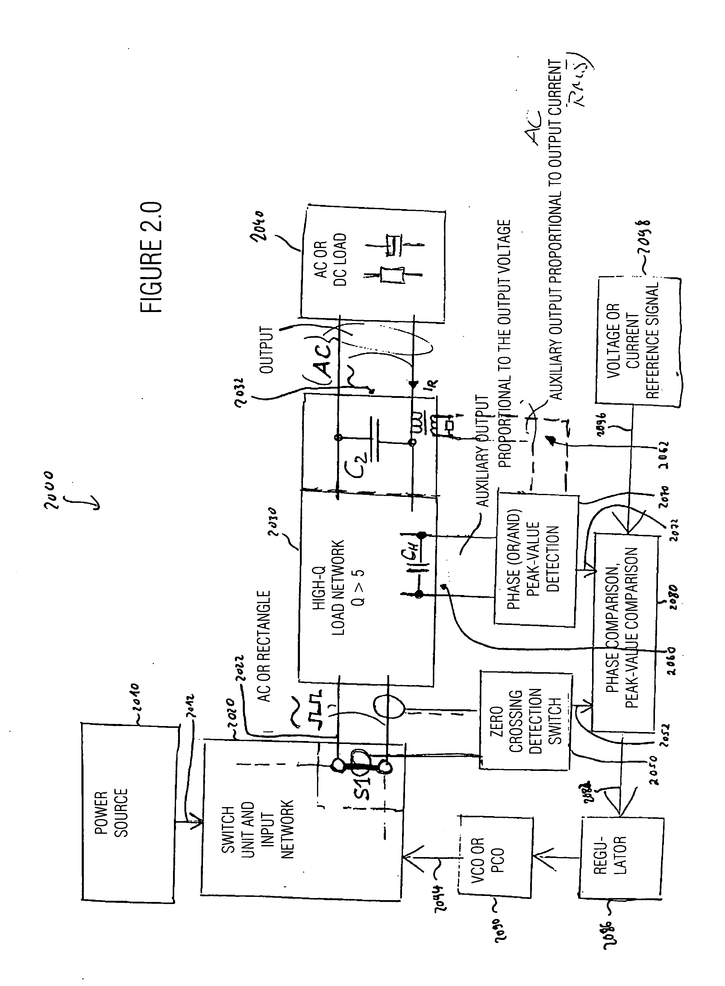
The present invention provides a control circuit for a resonance converter that can operate at low cost and with low expense. The control circuit uses an auxiliary signal from the resonant transformer arrangement to determine both the frequency with which the switch unit is switched and the turn-on moments of the switches. This allows for reliable regulation at low expense. The control circuit includes a phase detector, a synchronizer, a detector, a regulator, and a synchronizer. The invention provides a solution for regulating a resonance converter using a single auxiliary signal.

Problems solved by technology

What is disadvantageous is the high level of power dissipation of conventional transformers which arises here, as well as the structural height of conventional electromagnetic transformers, which is several millimeters and is a factor of interference for small powers of up to about 100 Watts, but in particular up to 10 Watts.
In addition, the technological basic expense for constructing integrated magnetics in the power range below about 50 Watts is clearly too high in comparison with a discretely structured circuit.
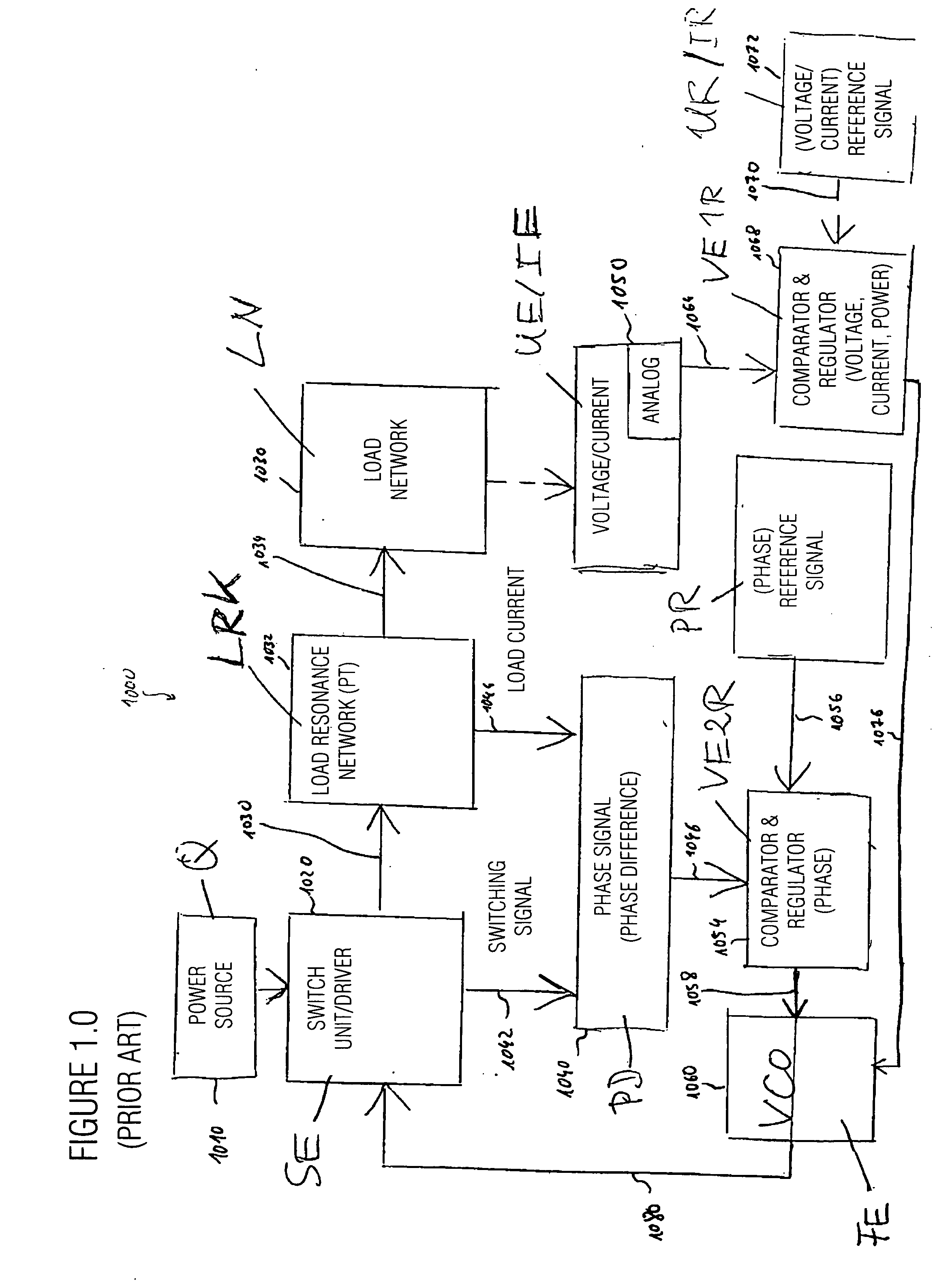
However, a disadvantage of this configuration is that even though the power present at a load fed with alternating current may be regulated via this phase shaft and / or phase difference, the load-circuit elements L and C must be known with a relatively high level of precision for a certain power to be set.
If, however, the value of L is not known, the power cannot be adjusted in an exact manner.
However, the input voltage range is limited, and the transformation ratio, or transmission ratio, of the converter causes an upward transformation.
Thus, two feedback circuits are required which also do not achieve galvanic separation between input and output.
However, in addition to a phase detector, which compares the phase between a switch voltage and a load current, a rectifying circuit is also used, which resistively loads the tapping of the load (sense resistor), and which would thus corrupt the signal of the load circuit if one wanted to couple out, or extract, or tap, this phase signal from the piezo transformer itself.
Therefore, one cannot achieve galvanic separation between the load and the input without using an additional optocoupler or another galvanically separating coupling circuit, which is also not required in the application set forth in the document mentioned.
However, by doing this, a current from the transformation network of the PT is not included in the regulation, so that a galvanic separation of this circuit without galvanically separating feedback elements is not possible, since a output quantity, or variable, is always required for regulation (frequency and duty cycle).
This circuit is also not suitable for galvanic separation without feeding-back elements from the output to the input.
This configuration, however, entails major disadvantages.
In this case, the output voltage is not so easy to regulate in a dynamic manner.
However, what is disadvantageous is that it is necessary to generate the load current from an additional device which acts as a transformer and is not already included in the load circuit.
With downward-transforming applications, however, a loading at the auxiliary output by a resistive load or a rectification is problematic, since one would have to keep the voltage at a correspondingly low level to realize low-loss tapping.
Consequently, however, the signal-to-noise ratio is too small to be able to evaluate the auxiliary signal in a reliable manner.
If, however, the input voltage is also changed on a large scale, the publication mentioned offers no satisfying solution.
In addition, it is not possible to detect, via the phase signal of the output or of the auxiliary output which has thus been generated, whether zero-voltage switching (ZVS) is still possible, or whether, for example with a small load and a high input voltage, the relative turn-on time approaches zero, so that continuous operation is no longer possible, and so that one would have to switch to burst mode.
So far, there have been no fundamental technical solutions and suggestions for this which enable operation of various topologies of a load resonance converter using one and the same control principle.
In addition, there has so far been no useful technical solution to using a load circuit at the same time for supplying the control circuit when no additional auxiliary tappings are to be provided for supplying the control power and when, at the same time, the load current is not to be corrupted by such an auxiliary current supply with regard to its detection in terms of amplitude and phase position.
Furthermore, there has so far been no technical solution to detecting a variable proportional to the output voltage, in a manner in which it is galvanically separate from the output, such that it is neither electrically connected to a potential of the output voltage nor to a potential of the input voltage at the same time, but may be evaluated at any electrical potential desired, so that the two input electrodes may be guided via a voltage supply circuit, connected upstream from the piezo transformer, for supplying the control circuit, rather than also having to be connected, for example, at the reference potential of the control circuit, which is required for evaluating this auxiliary voltage proportional to an output voltage, the detection being irrespective of whether the output voltage is a pure alternating voltage or a trapezoid or oblong alternating voltage which acts toward the load via a rectifying circuit, and the amplitude of which corresponds to the direct load voltage.

Method used


Image

  • Control circuit for a switch unit of a clocked power supply circuit, and resonance converter
  • Control circuit for a switch unit of a clocked power supply circuit, and resonance converter
  • Control circuit for a switch unit of a clocked power supply circuit, and resonance converter

Examples


Embodiment Construction

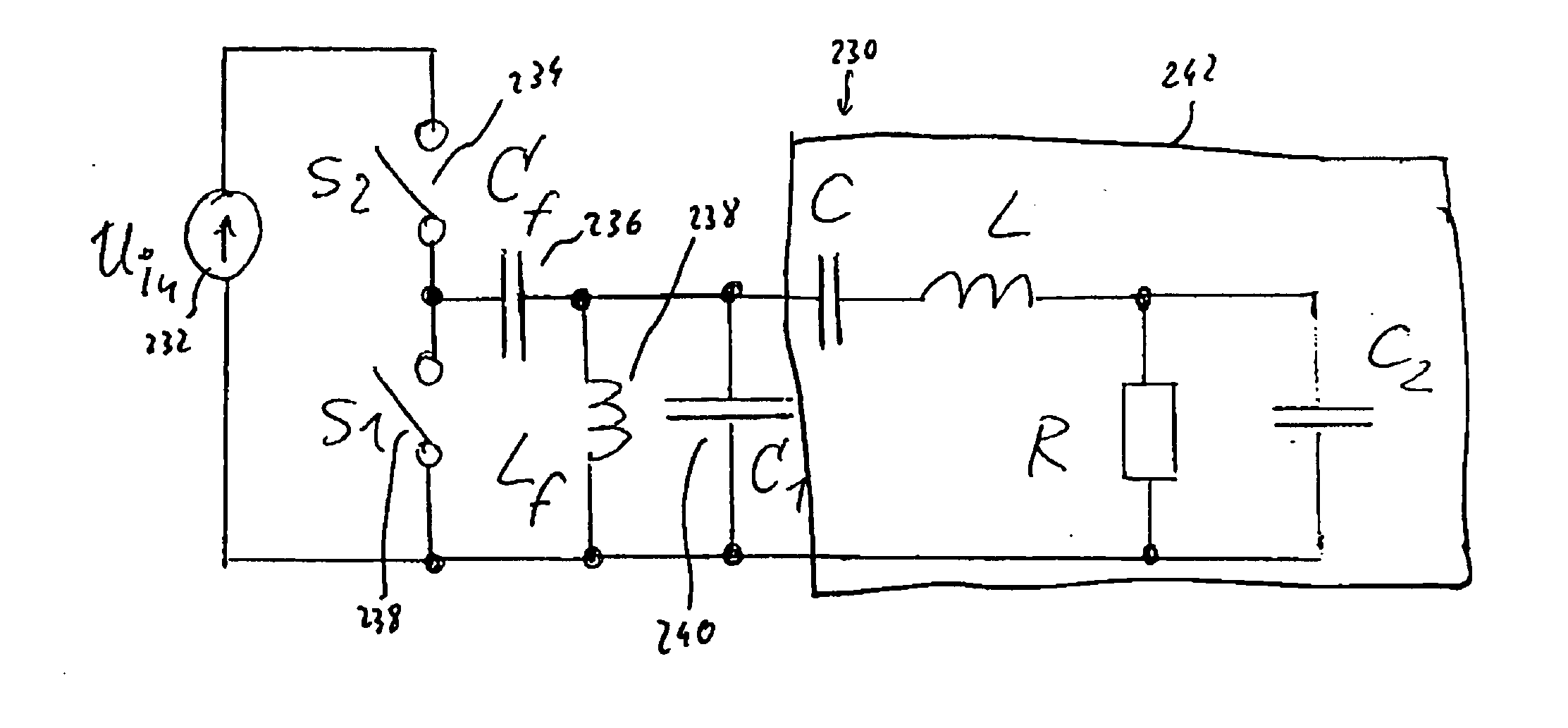
[0134] To facilitate understanding of the present invention, various circuitries will be described below which enable generation of input-side excitation of a resonant transformer arrangement. The circuitries mentioned do indeed form part of the prior art, but it has turned out that they exhibit particular advantages specifically in connection with the inventive control concept, or regulation concept. All circuitries described using FIGS. 1A, 1B, 1C, 2A, 2B, 2C, and 2D may therefore form an input network of the circuitries according to FIGS. 2.0, 2.1, 3F, 3G, 3H, 5, 6, 9, 12, 13B, 14, 16.

[0135] For example, FIG. 1A depicts a circuit diagram of a half-bridge circuit for generating input-side excitation for a resonant transformer arrangement.

[0136] The circuitry of FIG. 1A is designated by 100 in its entirety. Circuitry 100 includes a voltage source 110, the first terminal of which is coupled to a first input node 114 of the resonant transformer arrangement via a switch 112 (S2). A ...


PUM


Abstract

A control circuit for a switch unit of a clocked power supply circuit, the switch unit being designed to effect input-side excitation of a resonant transformer arrangement, comprises an input for receiving an auxiliary signal from the resonant transformer arrangement. The auxiliary signal exhibits an essentially fixed phase relation to a load alternating current flowing through a resonant circuit of the transformer arrangement. The control circuit further comprises a phase detector designed to detect reference crossing moments when the auxiliary signal crosses a predefined reference value, a driver controllable to switch the switch unit, and a synchronizer designed to synchronize a turn-on of the switch unit by the driver with regard to a phase position with the auxiliary signal so as to achieve a turn-on of the switch unit within a predetermined time interval around a zero crossing of a voltage present across the switch unit, or of a current flowing through the switch unit. The synchronizer is further designed to receive information about the reference crossing moments from the phase detector, and to provide a turn-on signal to the driver with a fixed phase delay at the reference crossing moments, so as to define turn-on moments at which the driver is to turn on the switch unit. The control circuit further comprises a detector designed to determine an amplitude information which depends on an amplitude or a mean value of the auxiliary signal, and a regulator designed to change an operating frequency in dependence on the amplitude information supplied by the detector, and to determine a period duration between turn-off moments at which the driver is to turn off the switch unit as a reciprocal of the operating frequency. An inventive resonance converter enables independent control of frequency and turn-on moments, or duty cycle, and thus enables a particularly efficient operation of the resonance converter, and a particularly precise regulation.

Description

CROSS-REFERENCE TO RELATED APPLICATION [0001] This application claims priority from German Patent Application No. 102005023686.3, which was filed on May 23, 2005, and from German Patent Application No. 102006022845.6, which was filed on May 16, 2006, and which are incorporated herein by reference in their entirety. BACKGROUND OF THE INVENTION [0002] 1. Field of the Invention [0003] The present invention generally relates to a control circuit for a switch unit of a clocked power supply circuit as well as to a resonance converter, specifically to a regulated resonance converter. [0004] 2. Description of Prior Art [0005] In a multitude of applications, it is required to generate an output voltage or an output current because of an input-side energy source, it typically being required to regulate the output voltage, the output current or the output power. [0006] Solutions which are current today in terms of operating regulated power supply units are flyback converters with galvanic sepa...

Claims


Application Information

Patent Timeline
Patent Type & Authority Applications(United States)
IPC IPC(8): H02M3/335
CPCH02M3/33507Y02B70/1491H02M2001/0058Y02B70/1433H02M1/0058Y02B70/10
Inventor RADECKER, MATTHIASBISOGNO, FABIOHERFURTH, MICHAEL
Owner FRAUNHOFER GESELLSCHAFT ZUR FOERDERUNG DER ANGEWANDTEN FORSCHUNG EV
Why Eureka
Eureka Blog
Learn More