
Color display unit

Inactive Publication Date: 2006-12-21
SEIKO INSTR INC
View PDF6 Cites 25 Cited by
  • Summary
  • Abstract
  • Description
  • Claims
  • Application Information

AI Technical Summary

Benefits of technology

[0004] It is an object of the present invention to provide a color display unit having a wide range of color reproduction and low power consumption, with a simple structure, and without causing element deterioration.
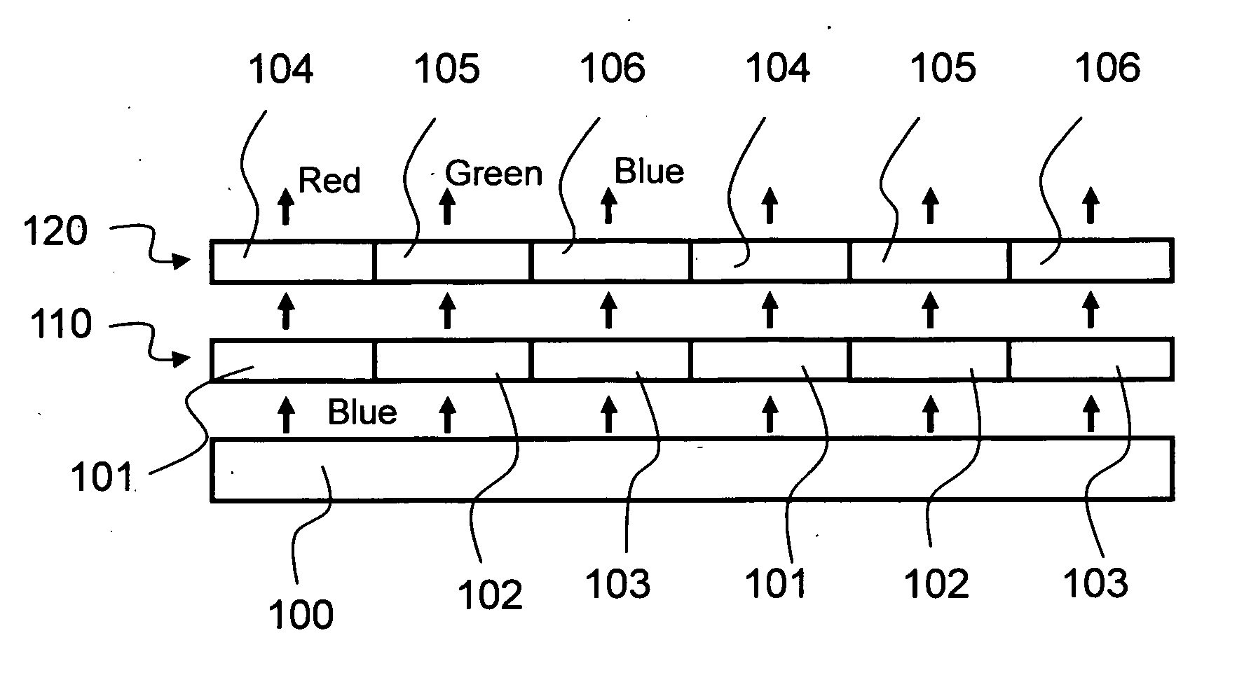
[0005] A color display unit of the present invention for solving the above described problems comprises a blue light source for generating blue light, a color conversion layer having a red color region for converting the blue light generated by the blue light source to red light, a green color region for converting the blue light to green light, and a blue color region for transmitting the blue light, arranged on a flat surface, and a pixel switch structure for ON / OFF control of transmission of the blue light for each of the red color region, green color region and blue color region in response to an image signal. With this type of structure, a color image is displayed using converted red light and green light, and blue light, which means that it is possible to display an image over a wider color reproduction range with high efficiency. Here, by having a structure where the red color region is a red fluorescent material layer and the green color region is a green fluorescent material layer, it becomes possible to use blue light as excitation light for the fluorescent material of each fluorescent material layer, and it is possible to avoid deterioration of the display elements.
[0006] Also, a red filter for passing red light and a green filter for passing green light are provided for respective transmitted light of the red color region and the green color region. With this type of structure, it is possible to improve color purity of red light and green light used in color display, and it becomes possible to display a color image having a wider color reproduction range. Further, it is possible to provide a blue color filter for selectively transmitting a blue wavelength range, so as to correspond to the blue color region.
[0007] Alternatively, a filter is provided to absorb the blue light wavelength region, so as top correspond to the red color region and the green color region. In this way, it becomes possible to perform display with good color purity even if a color filter is not used.
[0010] Also with the present invention, a blue light source for emitting blue light is made a blue LED. With these measures, it is possible to realize high brilliance color image display with high reliability.

Problems solved by technology

However, with the conventional structure where fluorescent material is mixed inside a color filter, excitation light is ultraviolet, which means that as well as the fact that ultra violet light absorption inside the liquid crystal elements is large giving bad efficiency, ultra violet light influences the liquid crystal molecules or liquid crystal orientation, and there is a danger of promoting element deterioration.

Method used


Image

  • Color display unit
  • Color display unit
  • Color display unit

Examples


embodiment 1

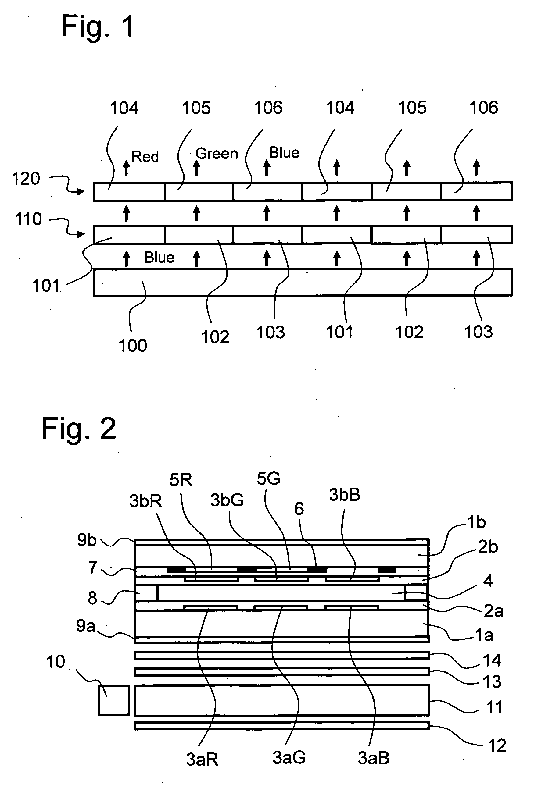
[0030] The cross sectional structure of the display unit of this embodiment is shown schematically in FIG. 2. As shown in FIG. 2, the liquid crystal element is configured with a liquid crystal layer 4 enclosed in a gap between a glass substrate 1a and an opposing substrate 1b. Transparent electrodes 3aR, 3aG, 3aB, and an orientation film 2a on the transparent electrodes, are formed on the glass substrate 1a. On the other hand, a red fluorescent material layer 5R and a green fluorescent material layer 5G are formed on the opposing substrate. A black matrix 6 is formed in gaps between these fluorescent material layers, except for the blue color region. Formation regions for the red fluorescent material layer 5R, the green fluorescent material layer 5G and the black matrix 6 are flattened using a flattening layer 7. Transparent electrodes 3bR, 3bG and 3bB constituting pixel electrodes are formed on the flattening layer 7 opposite to the transparent electrodes 3aR, 3aG and 3aB. An orien...

embodiment 2

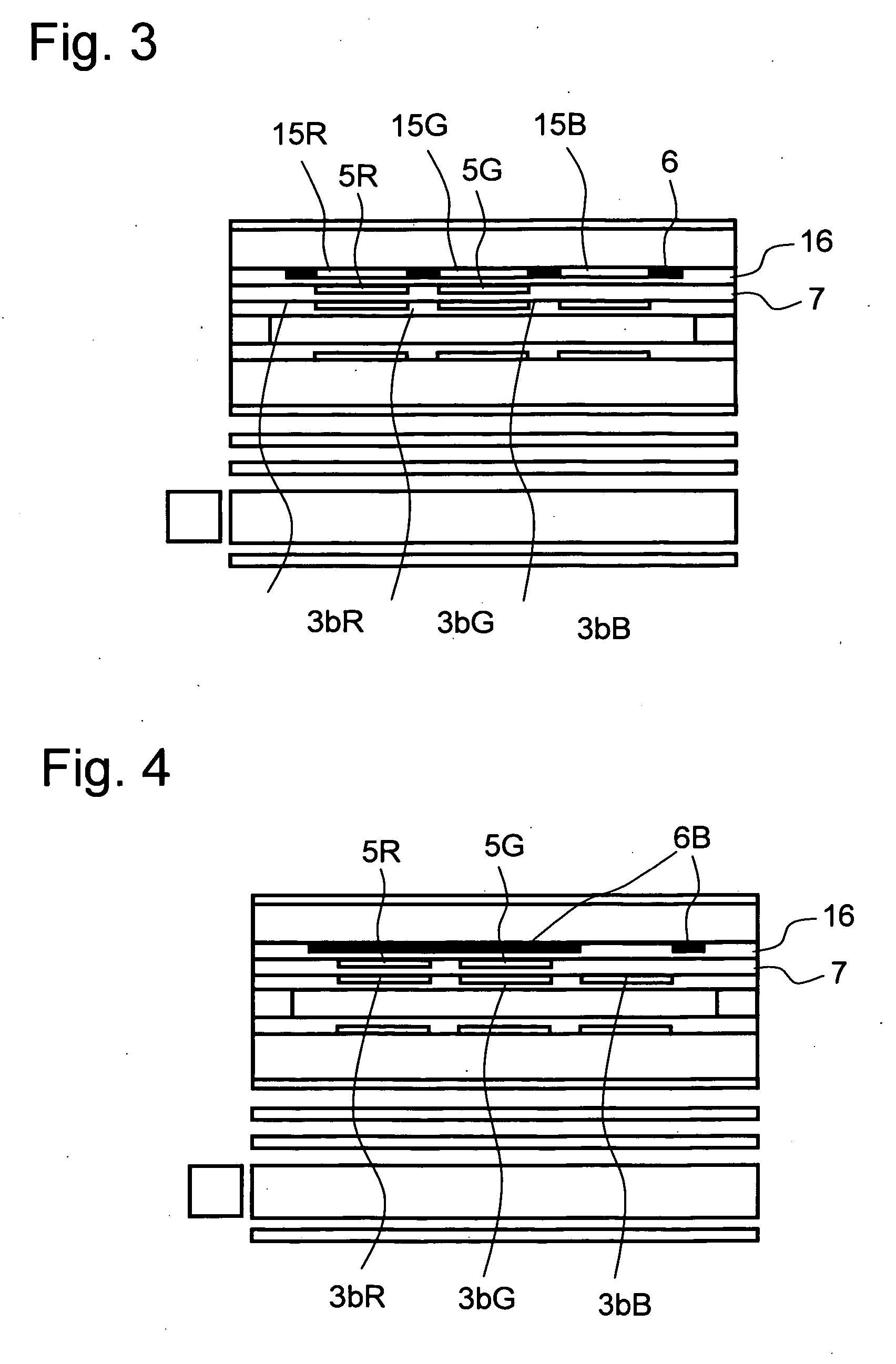
[0035] The cross sectional structure of the display unit of this embodiment is shown schematically in FIG. 3. This embodiment is different from embodiment 1 in that a red color filter 15R is formed corresponding to the red color region, a green color filter 15G is formed corresponding to the green color region, and a blue color filter 15B is formed corresponding to the blue color region. These color filters are formed corresponding to each color region, with a macromolecular base material containing colorant or pigment so as to selectively transmit only the respective red wavelength range, green wavelength range or blue wavelength range. As shown in the drawing, with this embodiment the color filters 15R, 15G and 15B are flattened with a second flattening layer 16, and the red fluorescent material layer 5R and the green fluorescent material layer 5G are formed on this flattening layer. The black matrix 6 is also formed in a gap between each of the color filters.

[0036] The efficienc...

embodiment 3

[0038] The cross sectional structure of the display unit of this embodiment is shown schematically in FIG. 4. This embodiment us different from embodiment 2 in that color filters for each color are not provided, and a blue mask 6B for cutting the blue wavelength (450-480 nm) is provided. The blue mask 6B is open only at blue color regions, and elsewhere exists on the red color region and the green color region. Therefore, a wavelength component in the blue color region contained in light that has transmitted the red color region and the green color region is cut by this blue mask 6B. That is, equivalent operation to that the red color filter 15R and the green color filter 15G of embodiment 2 is obtained. According to this type of structure, it is possible to do away with the color filter layers, and it is possible simplify the manufacturing process.

[0039] The blue mask 5B has a peak wavelength of from 450 nm to 480 nm, and has transmission characteristics such that so-called blue v...


PUM


Abstract

There is provided a color display unit having a wide range of color reproduction and low power consumption, with a simple structure, and without causing element deterioration. The display unit comprises light source means for generating blue light, a color conversion layer having a red color region for converting the blue light generated by the light source means to red light, a green color region for converting the blue light to green light, and a blue color region for transmitting the blue light as is, arranged on a flat surface, and a pixel switch structure for turning the blue light ON or OFF for each of the red color region, green color region and blue color region in response to an image signal.

Description

BACKGROUND OF THE INVENTION [0001] The present invention relates to a color image display unit used in mobile information units, such as mobile phones or mobile computers, or in large scale image apparatus such as desktop computers or household televisions [0002] Conventionally, small thin type low power consumption color liquid crystal display units have often been used as a color image display unit used in mobile information units such as mobile telephones or mobile computers. High brilliance low power consumption color liquid crystal display units are also spreading rapidly in the field of large-scale image display apparatus such as desktop computers and household televisions. These liquid crystal display units achieve smaller and thinner structures, and reduced power consumption with prolonged lifespan, compared to the case of conventional cold cathode tubes, due to the fact that a white LED is used as an illuminated light source. On the other hand, with a semi-transmissive liqu...

Claims


Application Information

Patent Timeline
IPC IPC(8): H01K1/30H01J5/16
CPCH01L27/322G02F1/133617H10K59/38G02F1/1335
Inventor KURIHARA, MAKOTODEJIMA, NORIHIROIGARASHI, KATSUYUKIHARA, MITSUYOSHI
Owner SEIKO INSTR INC
Learn More