Catheter System Having Imaging, Balloon Angioplasty, And Stent Deployment Capabilities, And Method Of Use For Guided Stent Deployment

Inactive Publication Date: 2006-12-14
SCI MED LIFE SYST
View PDF5 Cites 32 Cited by
  • Summary
  • Abstract
  • Description
  • Claims
  • Application Information

AI Technical Summary

Benefits of technology

[0005] Where removal of vascular deposits is not desired, endovascular grafts have been developed to enlarge an occluded vessel lumen, and to hold tissue in place or to provide a support for a graft while healing is taking place. Intraluminal endovascular grafting has been shown to provide an alternative to conventional vascular surgery. Endovascular grafting involves percutaneous insertion of a prosthetic graft into a blood vessel, and such devices are generally delivered via a catheter to a region of interest within the vascular system. These techniques have the clear advantage over conventional surgery of eliminating a need for surgically exposing, replacing, incising, removing, or bypassing a defective blood vessel. Several structures have been shown to have use as intraluminal prosthetic grafts. These structures include coiled stainless steel springs, helically wound coil springs, and expanding stainless steel stents.
[0007] A number of specific designs for ultrasonic imaging catheters have been described. An early design is illustrated in U.S. Pat. No. 4,794,931, where the mechanical components of the imaging system are located within a housing at the distal end of the catheter. The housing includes a fixed guidewire at its distal tip, which is used to position the catheter within the vascular system. While the use of such fixed-guidewire designs can provide excellent image quality, under some circumstances it is desirable to use an “over-the-wire” design where the catheter may be introduced over a separate (movable) guidewire. The use of a movable guidewire offers certain advantages, including improved steering capability through narrow regions and easier catheter exchange, e.g., substitution of an interventional catheter for the imaging catheter.
[0008] Various designs for removable and non-removable imaging cores have also been described. Specific examples are set forth in Sieben et al., U.S. Pat. No. 5,243,988, and in Sieben et al., U.S. Pat. No. 5,353,798, both of which are incorporated herein by reference. These devices generally include an imaging core designed to operate within a guidewire lumen of therapeutic catheters which accept a guidewire of 0.018 inch or smaller. In one embodiment, the device consists of a fixed, non-removable proximal hub apparatus, which is not disconnectable from the imaging core. The main body of the device consists of the drive shaft, and this shaft provides for ease of loading the imaging core into the therapeutic catheter, and steady rotational movement in order to obtain an image without distortion.
[0016] Another alternative catheter has one or more lumens in the proximal region, and two or more lumens in the distal region of the catheter, wherein at least one of the proximal lumens is in communication with at least one of the distal lumens. In this embodiment, the guidewire occupies one lumen in the distal region and can remain in place during imaging. This design offers the convenience of imaging using a movable imaging core in the second distal lumen while the guidewire remains in place in the first distal lumen. Operations using this design save time associated with withdrawing and advancing of instruments through the various lumens, but suffer the small drawback of displaying an image having artifacts associated with the presence of the guidewire positioned at one location in the ultrasound scan.
[0017] The catheter of the present invention will allow for performance of rapid and convenient balloon angioplasty and imaging for guided placement of a prosthetic device or stent within a diseased vessel, while minimizing the need to reposition the catheter body between procedures. Additionally, the distal end of the catheter will be relatively narrow to allow for movement of the catheter into restricted spaces of the patient's vascular system and particularly into narrow regions and stenoses within the coronary arteries. Further, the catheter of the invention enables stent deployment in combination with balloon angioplasty and imaging, and will allow for a guided stent placement procedure.

Problems solved by technology

Localized accumulation of deposits within regions of the blood vessels may result in stenosis, or narrowing of the vascular channel.
When this occurs, blood flow is restricted and the person's health is at serious risk.

Method used


Image

  • Catheter System Having Imaging, Balloon Angioplasty, And Stent Deployment Capabilities, And Method Of Use For Guided Stent Deployment
  • Catheter System Having Imaging, Balloon Angioplasty, And Stent Deployment Capabilities, And Method Of Use For Guided Stent Deployment
  • Catheter System Having Imaging, Balloon Angioplasty, And Stent Deployment Capabilities, And Method Of Use For Guided Stent Deployment

Examples


Embodiment Construction

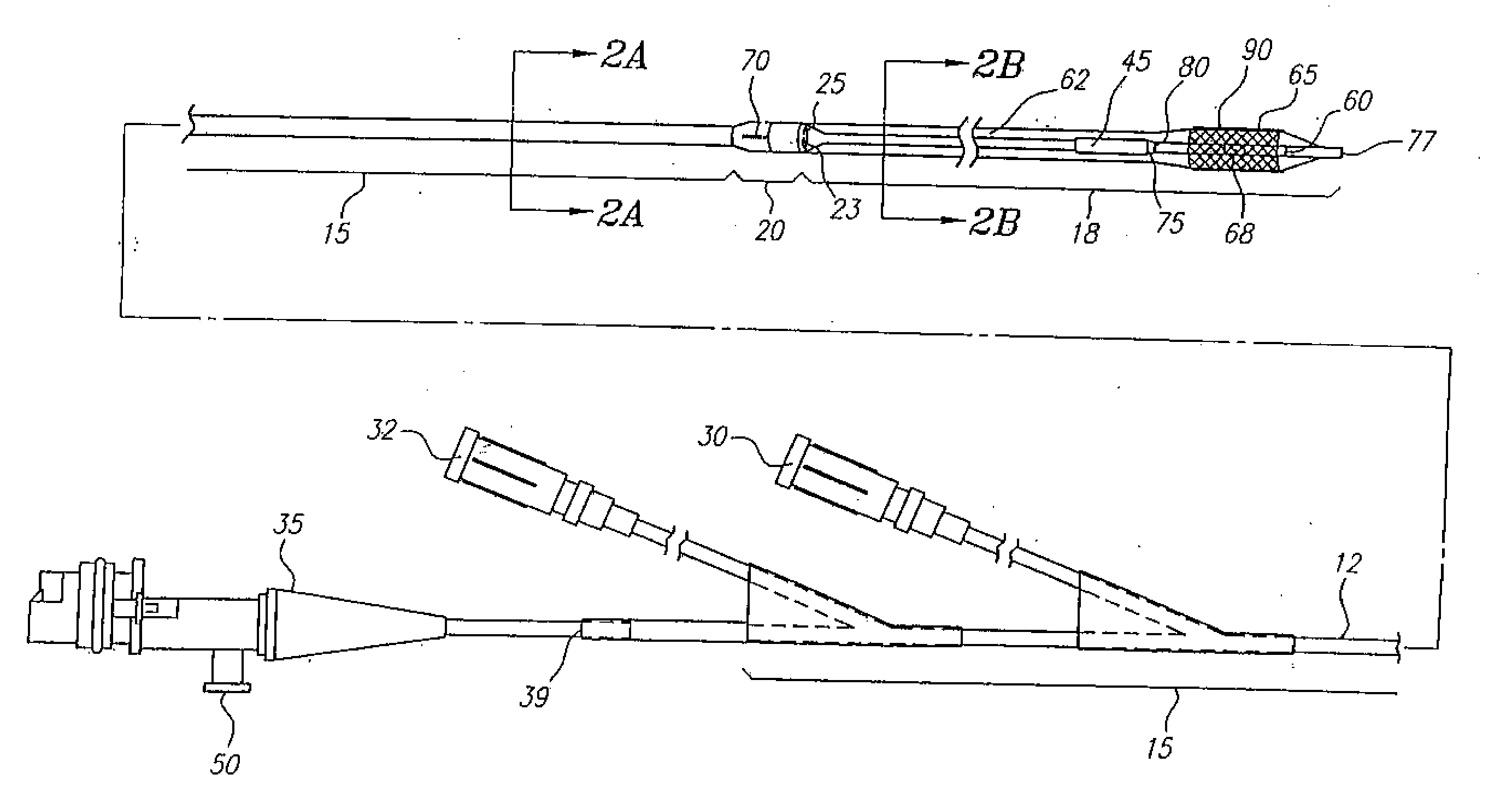
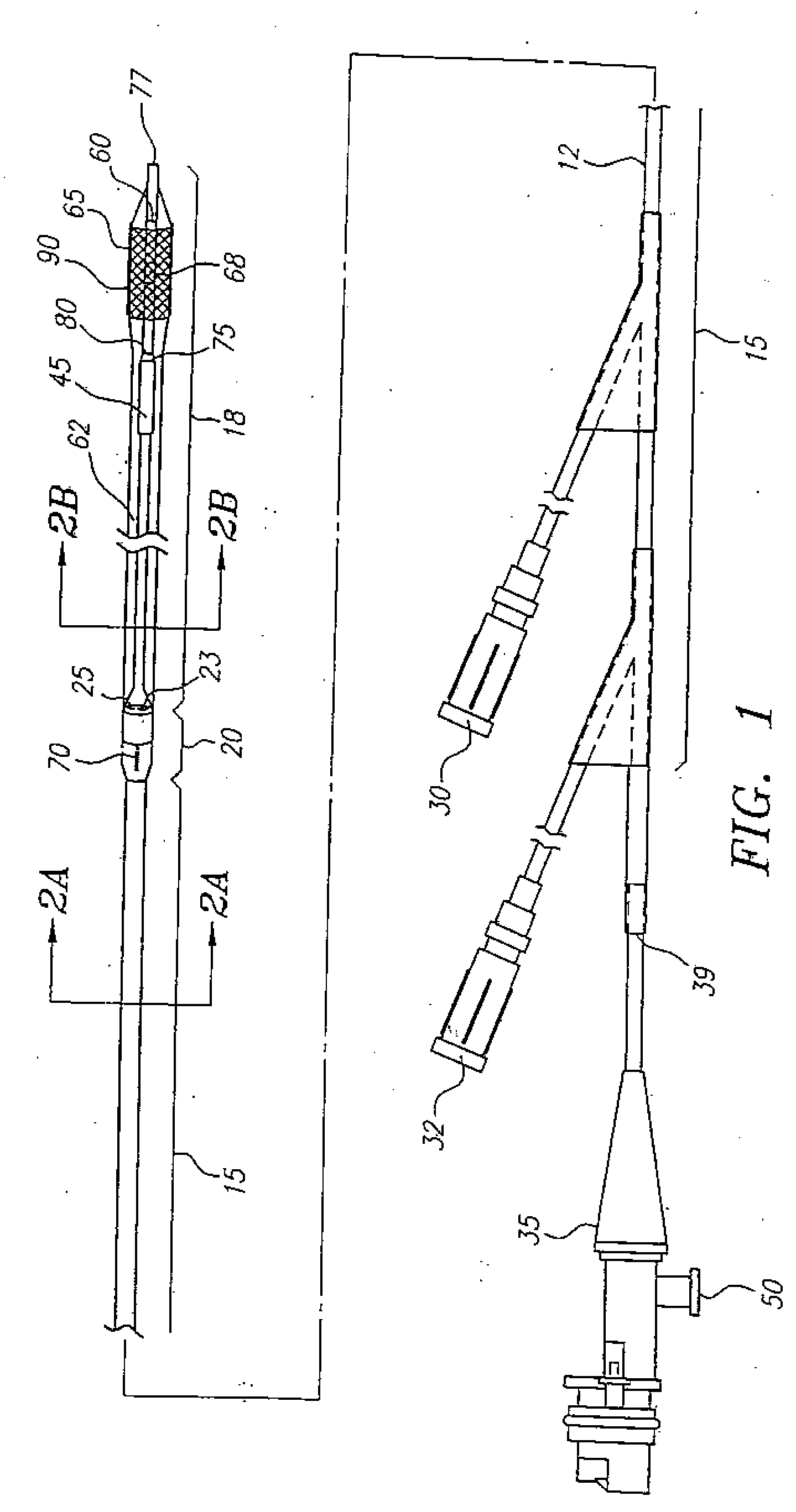
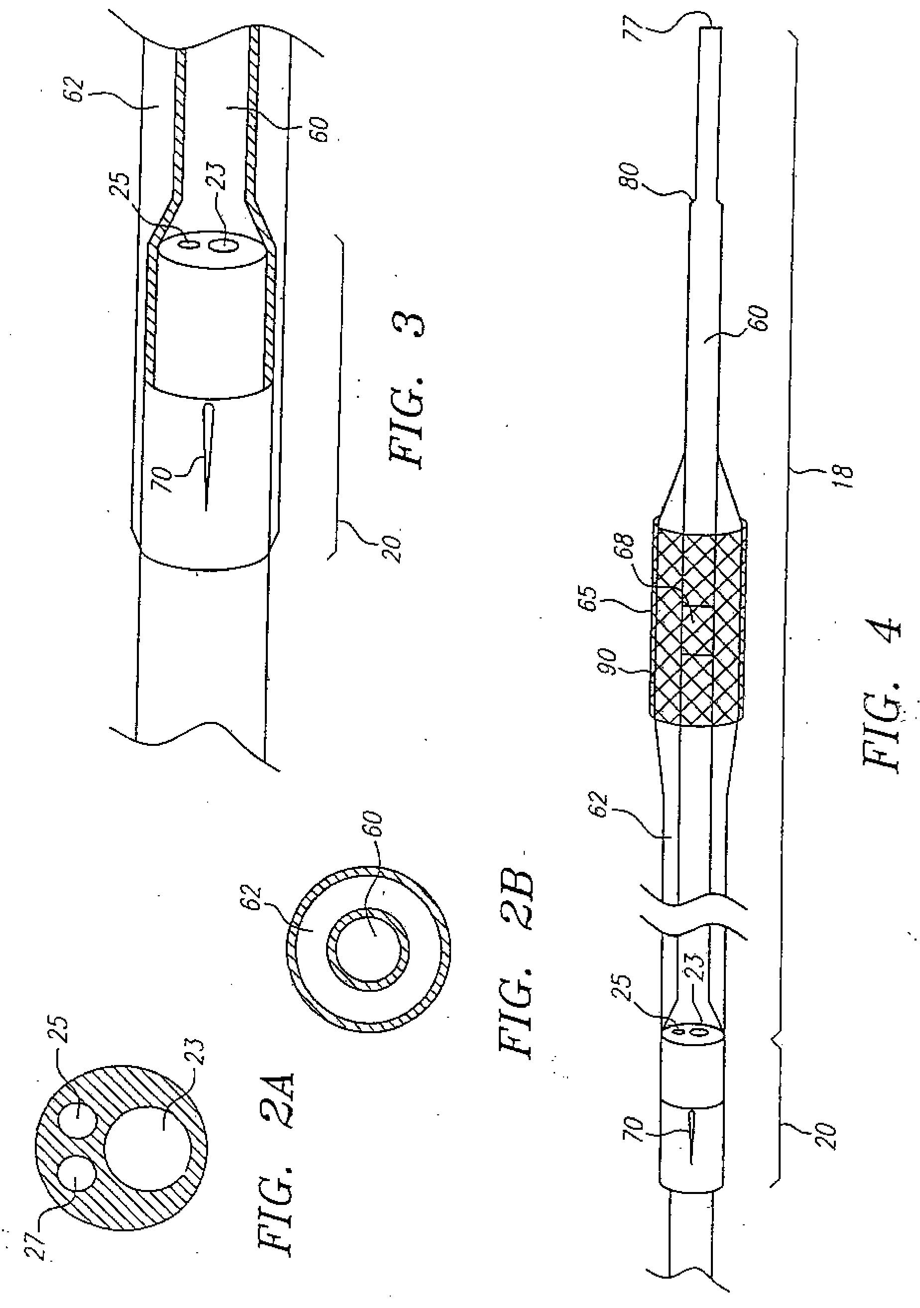
[0041] The prosthetic devices which are preferred for use with the catheters and methods described herein include stents, and particularly the Palmaz-Schatz stent which is available from Johnson & Johnson. Stents for use herein are disclosed in Palmaz, U.S. Pat. No. 4,733,665, and Cragg, U.S. Pat. No. 5,405,377, both of which are expressly incorporated herein by reference. Briefly, these stents include a tubular-shaped member having first and second ends and a wall surface disposed between the first and second ends, the wall surface being formed by a plurality of intersecting elongate members, at least some of the elongate members intersecting with one another intermediate the first and second ends of the tubular-shaped member; the tubular-shaped member having a first diameter which permits intraluminal delivery of the tubular-shaped member into a body passageway having a lumen; and the tubular-shaped member having a second, expanded diameter, upon the application from the interior ...


PUM


Abstract

A catheter system has a balloon angioplasty device disposed about a common lumen near its distal end. The balloon catheter is pre-fitted with a stent which is deployed when the balloon is inflated. The common lumen is in communication with multiple lumens within a proximal region of the catheter body to allow for positioning of the catheter over a movable guide wire and convenient delivery of imaging or interventional devices to a desired region of a body passageway being treated. The procedure for stent deployment optionally includes steps of imaging a lumen by ultrasound before and after stent deployment to identify the site at which a stent is needed, to confirm that the stent is being and has been deployed at a longitudinal position which does not overlap a branched segment of the body passageway, and to ensure that the stent has been radially opened to an optimum diameter.

Description

CROSS REFERENCE TO RELATED APPLICATIONS [0001] This application is a continuation of U.S. application Ser. No. 10 / 306,976, filed Nov. 27, 2002, which is a continuation of U.S. application Ser. No. 09 / 384,846, now U.S. Pat. No. 5,749,848, filed Aug. 27, 1999, all of which are incorporated herein by reference.BACKGROUND OF THE INVENTION [0002] The present invention relates generally to guided stent deployment using a catheter system for imaging and treatment of stenoses within a body passageway, including a patient's vascular system, and more particularly to a catheter system in which an angioplasty balloon can be used to deploy a stent device, said catheter system further including an imaging element for use within a region of a blood vessel so that placement and expansion of the stent can be observed. BRIEF SUMMARY OF THE INVENTION [0003] Arteriosclerosis, also known as atherosclerosis, is a common human ailment arising from the deposition of fat-like substances, referred to as athe...

Claims


Application Information

Patent Timeline
IPC IPC(8): A61F2/06
CPCA61F2/958
Inventor JANG, YUE-TEH
Owner SCI MED LIFE SYST
Why Eureka
Try Eureka