
IC packaging technique

a technology of integrated circuits and packaging techniques, applied in the direction of electrical equipment, semiconductor devices, semiconductor/solid-state device details, etc., can solve the problems of reducing the defect rate of thermosetting materials, limited number of suitable i/o pins, and inability to recycle thermosetting materials, etc., to achieve the effect of reducing the defect ra

Inactive Publication Date: 2006-12-07
POWER DIGITAL CARD +1
View PDF6 Cites 4 Cited by
  • Summary
  • Abstract
  • Description
  • Claims
  • Application Information

AI Technical Summary

Benefits of technology

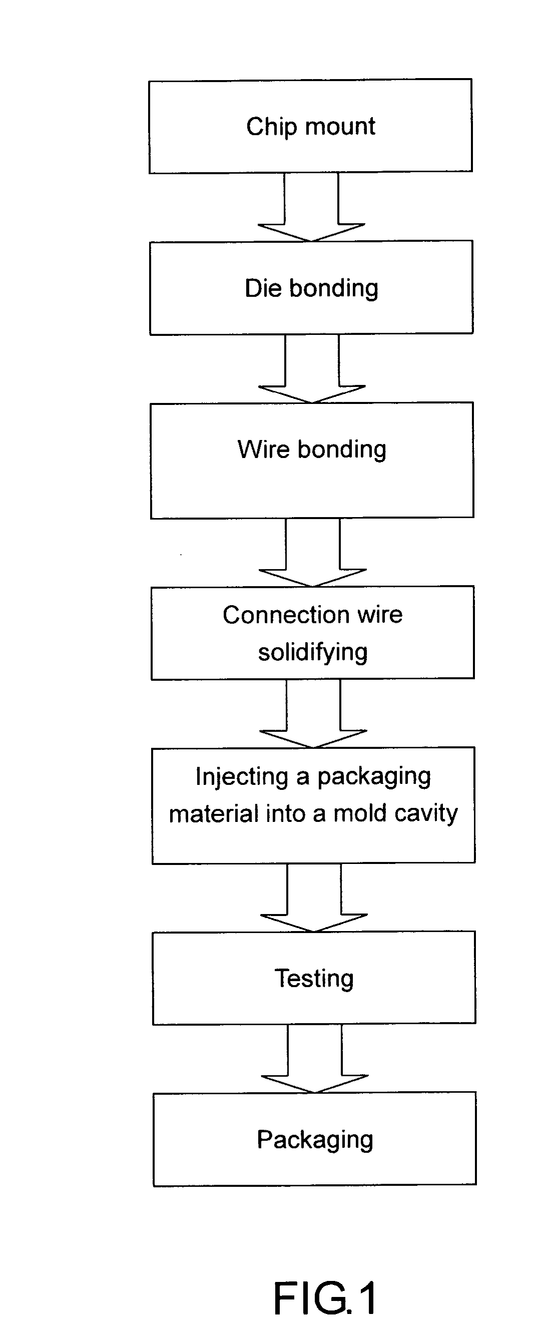
[0007] The primary-object of the present invention is to provide an IC packaging technique for meeting requirements of environmental protection and with a stable packaging process, wherein the packaging process includes a die bonding on an IC chip mount, a wire bonding, and a solidifying to a connection wire, followed by injecting a packaging material into a mold cavity, and a final testing and packaging. The packaging material to be injected can be a recyclable and environmental benign plastic material, i.e., a thermal plastic material, such as an ABS, a PE, to fulfill requirements of environmental protection. In addition, the packaging can be accomplished with a smaller injection pressure and a lower temperature during the process of packaging, thereby reducing a defect rate due to damage to a circuit wiring.

Problems solved by technology

Techniques of IC architecture applying an IC chip mount, which are often seen in the existing market, are all limited to numbers of suitable I / O pins and a tolerable range of electronics properties.
As a thermosetting material is used to package existing IC chips, but the thermosetting material cannot be recycled for re-use, an environmental pollution will be generated definitely.

Method used


Image

  • IC packaging technique
  • IC packaging technique
  • IC packaging technique

Examples


Embodiment Construction

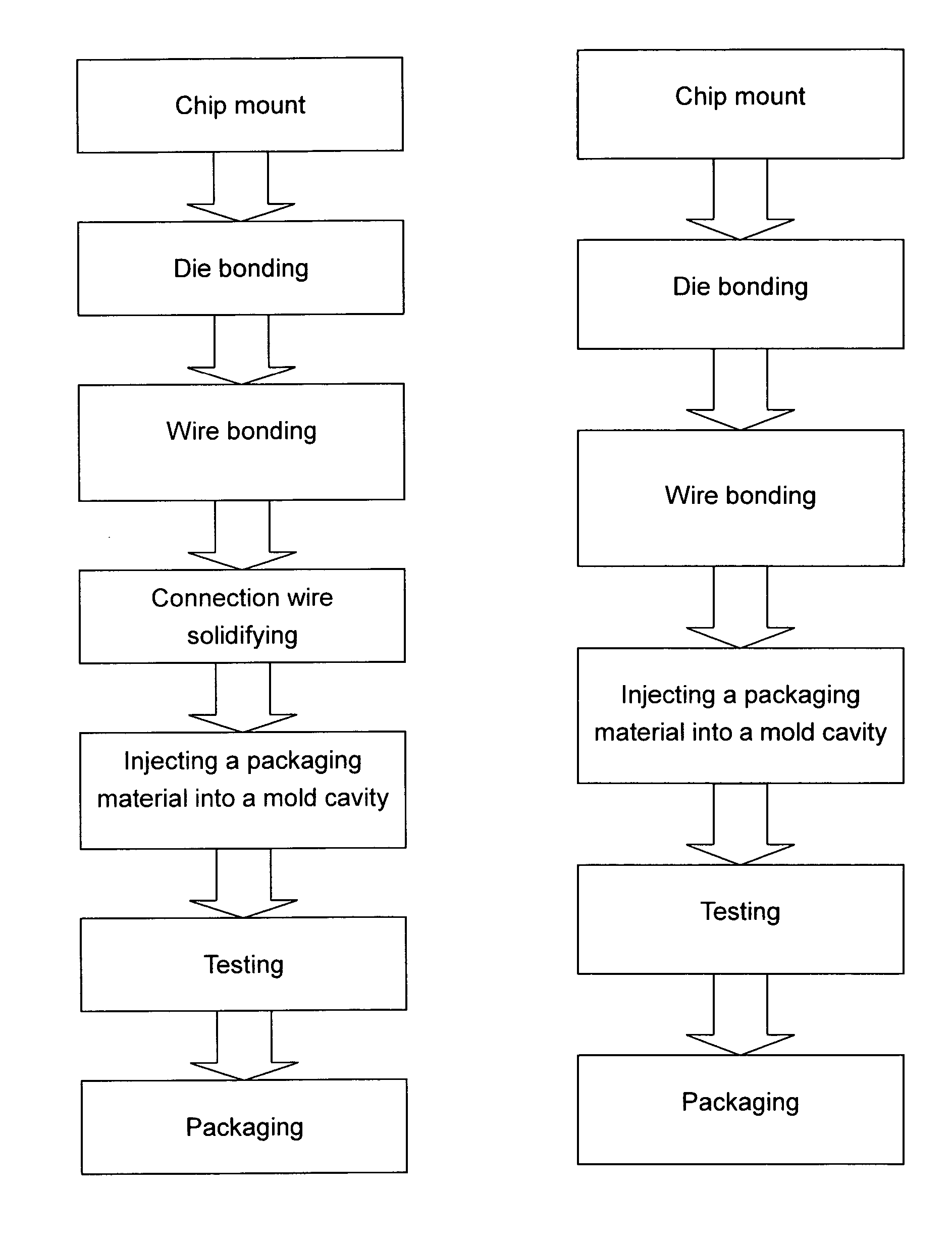
[0011] Referring to FIG. 1, it shows a flow diagram of implementation of the present invention. The IC packaging process of the present invention starts at a die bonding on a chip mount and then a wire bonding; following solidifying a connection wire, a packaging material is injected into a mold cavity, and finally a testing and packaging are performed. During the procedure of injecting the package material into the mold cavity, a thermal plastic material which meets requirements of environment protection is used for implementation.

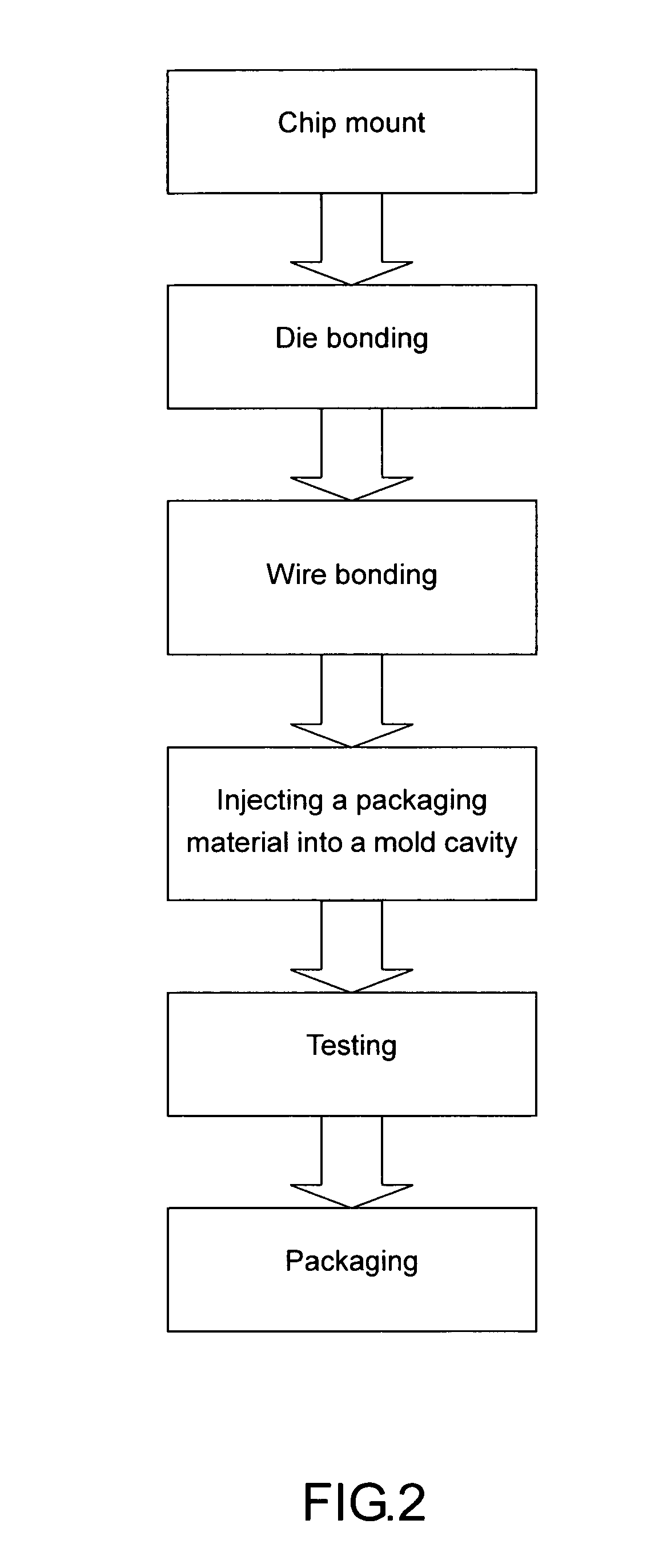
[0012] Under a condition of simple circuit wiring or that there is no concern about bonding, the engineering of solidifying the connection wire can be avoided definitely, and the injection of packaging material into the mold cavity can be proceeded directly (as shown in FIG. 2).

[0013] The IC packaging technique of the present invention actually serves as a comparison and improvement against shortcomings of a conventional packaging with a thermosetting m...


PUM


Abstract

An IC packaging technique uses a recyclable and environmental benign plastic material (such as a thermal plastic material) to perform packaging to an IC chip, in order to solve shortcomings of an inability of being recycled of a thermosetting material, an inability of reprocessing and repairing the IC, and a generation of environmental pollution. The thermal plastic material can be a low-temperature molding material such as an ABS or a PE. More particularly, the present invention can use a conventional plastic injection machine and a recyclable thermal plastic material to perform packaging, which overcomes a technical bottleneck of industries in high pressure and high temperature, so as to increase a stability and perfection rate to the IC chip packaging process, and to meet requirements of environmental protection.

Description

BACKGROUND OF THE INVENTION [0001] 1. (a) Field of the Invention [0002] The present invention relates to an IC (Integrated Circuit) packaging technique, and more particularly to a technique wherein a recyclable and environmental benign plastic material (such as a thermal plastic material) for replacing an existing thermosetting material used by industries, and especially a conventional plastic injection machine are used to package an IC chip, which not only overcomes a technical bottleneck of industries in high pressure and high temperature, but also increases a stability and perfection rate to a process of packaging, and especially meets requirements of environmental protection. [0003] 2. (b) Description of the Prior Art [0004] As the advancement of technology in the 21st century, electronic products are developed worldwide on the basis of an IC unit. The purpose of an IC manufacturing process is to provide a set of architecture to the IC, so as to enable the IC to achieve a stable...

Claims


Application Information

Patent Timeline
Patent Type & Authority Applications(United States)
IPC IPC(8): H01L23/58H01L29/10
CPCH01L23/293H01L2924/0002H01L2924/00
Inventor CHEN, CHIEN-YUAN
Owner POWER DIGITAL CARD
Learn More