
Combination scalpel blade

a scalpel blade and combination technology, applied in the field of scalpel blades, can solve the problems of inconvenient replacement of blades, inconvenient use, sharp disposable blades, etc., and achieve the effect of optimum flexibility, efficiency and economy

Inactive Publication Date: 2006-11-30
LOWE JOHN PATRICK TRUSTEE CHAPTER 7 CASE NO 09 51026 C IN THE UNITED STATES BANKRUPTCY COURT FOR THE WESTERN DISTRICT OF TEXAS SAN ANTONIO DIV
View PDF13 Cites 11 Cited by
  • Summary
  • Abstract
  • Description
  • Claims
  • Application Information

AI Technical Summary

Benefits of technology

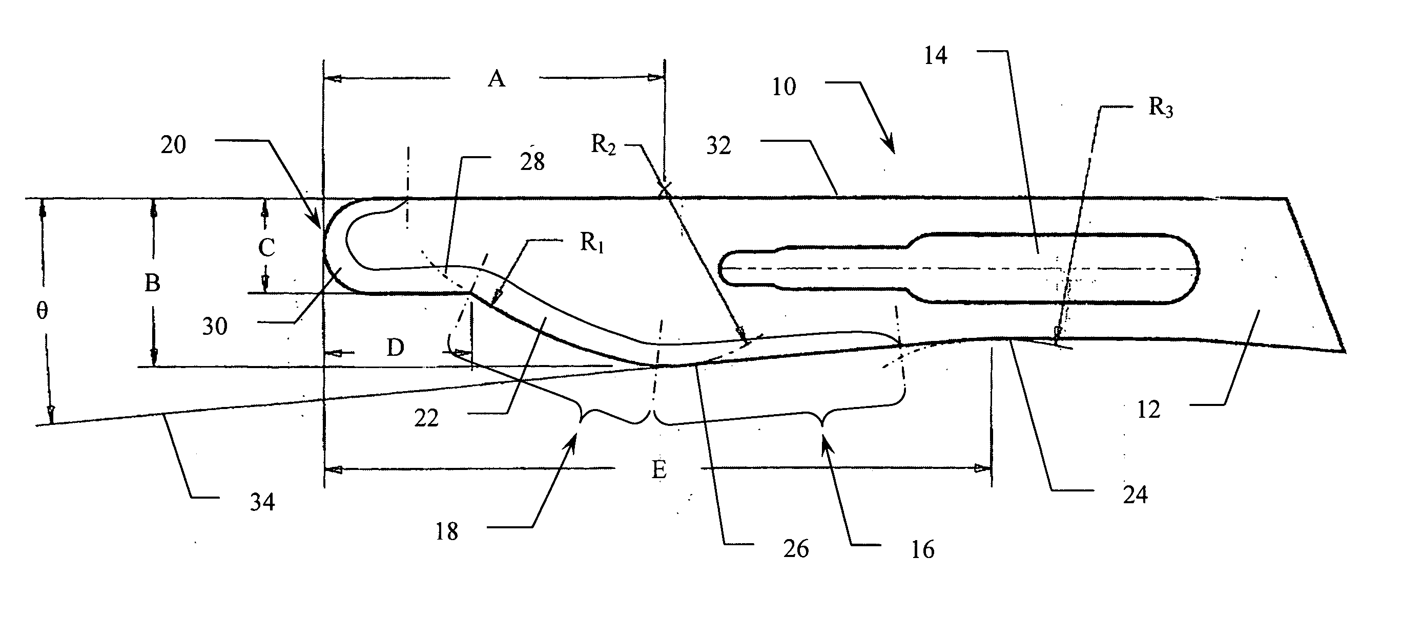
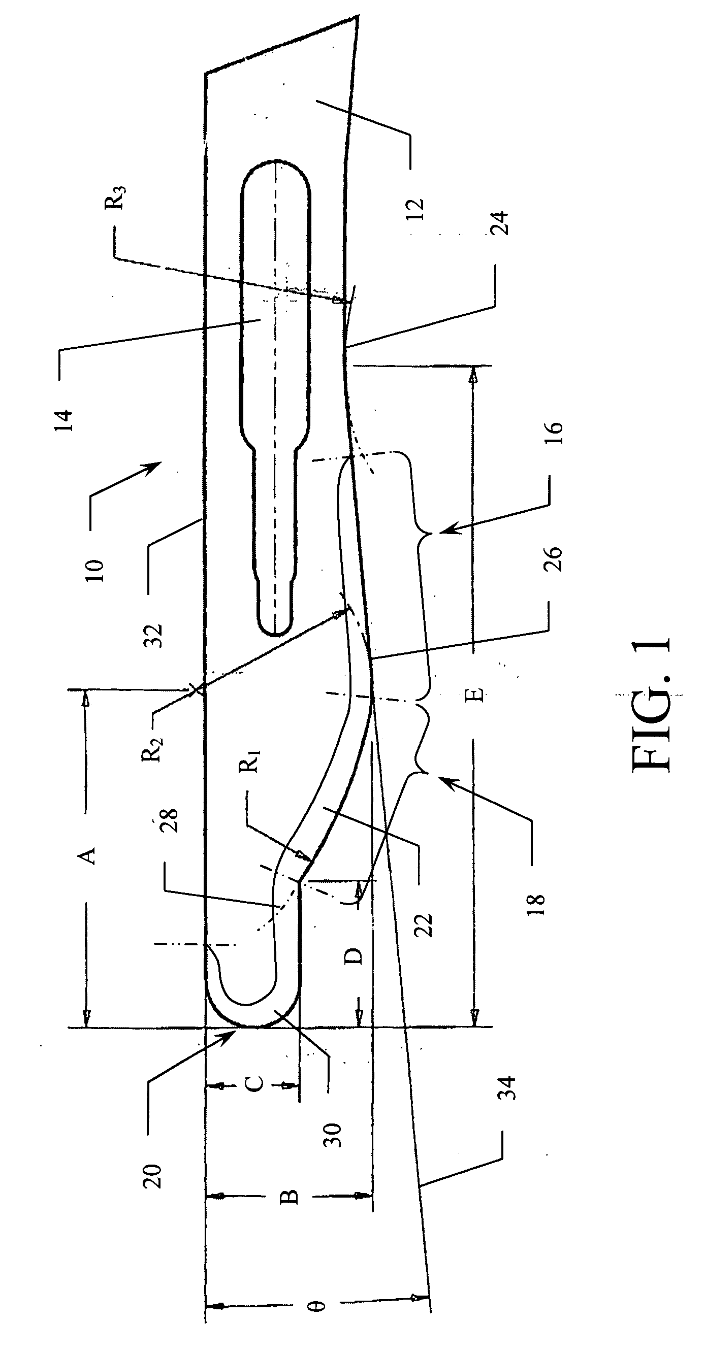
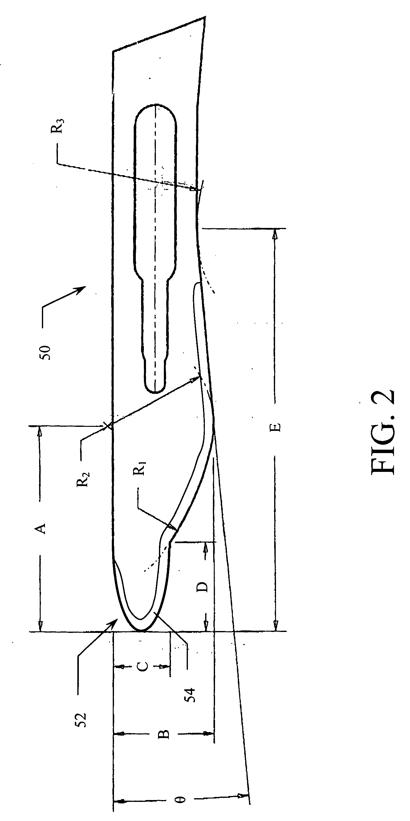
[0009] The surgical scalpel of the present invention is designed to provide an innovative combination of multiple cutting edges on one scalpel blade for optimum flexibility, efficiency, and economy. The scalpel blade is specifically designed for the types of cutting required for podiatric surgical procedures. More particularly, the scalpel blade has a handle attachment section and a plurality of cutting segments. The blade comprises a series of cutting edges: a single-edged longitudinal cutting segment extending from the handle attachment section; a single-edged curved cutting segment contiguous with and extending from the longitudinal cutting segment; and a double-edged end tip cutting segment contiguous with the curved cutting segment.
[0010] In a variety of podiatric surgical operations, it is frequently necessary to use a combination of scalpel blades in order to accomplish multiple types of cutting procedures. Three prior art scalpels are shown in FIGS. 3A, 3B, and 3C. FIG. 3A illustrates a #10 scalpel blade having a broad cutting edge with an extended longitudinal segment, FIG. 3B illustrates a #15 scalpel blade having a shorter cutting edge with a curved cutting segment, and finally, FIG. 3C illustrates a Beaver® blade having a pointed end tip cutting segment. For example, in a relatively simple procedure such as the removal of a plantar wart, the podiatrist may decide to perform surgical excision of the wart because this treatment has a high success rate with a relatively low rate of recurrence of the condition. The surgical removal or curettage of the wart, involves the scraping or cutting of the wart tissue with a scalpel. In this procedure, the podiatrist may use a straight sharp blade for the initial incision, a pointed or curved blade for the excision of the wart itself, and a curved sharp blade to scrape away any remnants of the wart tissue. It would therefore be desirable to have a single scalpel having a blade containing a combination of cutting surfaces such that the podiatrist could move smoothly from one step of the surgical procedure to the next without the delay and inefficiency involved in switching between scalpels or changing scalpel blades.
[0011] Similarly, the removal of a neuroma requires the podiatrist to perform multiple surgical steps for the removal of the damaged nerve. The podiatrist most often will incise the top of the patient's foot, locate the neuroma between the metatarsals behind the toes, and then cut the nerve and remove it. These steps require a blade for the initial incision, a blade for cutting the nerve, and a blade for removal of the nerve from the patient's foot. Once again, it would be helpful to have a single blade with multiple cutting edges to perform all of these tasks without having to utilize multiple scalpels or blades.

Problems solved by technology

One problem with the disposable / replaceable blade scalpel is that the work of replacing the blade with another requires meticulous precision due to the small blade size.
The disposable blades are sharp, curved, small and difficult to detach and replace.
Moreover, the used blade is often slippery from body fluids deposited on the blade during the surgical procedure.

Method used


Image

  • Combination scalpel blade
  • Combination scalpel blade
  • Combination scalpel blade

Examples


Embodiment Construction

[0020] Reference is made first to FIG. 1 for a detailed description of the structure and function of a scalpel blade according to the present invention. FIG. 1 illustrates a surgical scalpel blade 10 that includes a blade base 12 with a standard handle attachment slot 14. The combination blade 10 further includes a longitudinal cutting segment 16, a curved cutting segment 18, and an end tip cutting segment 20 positioned along the sharpened edge 22 of the blade. The structure of the blade is such that the three cutting surfaces are contiguous, with the longitudinal cutting segment 16 positioned next to the curved cutting segment 18 which is adjacent to the end tip cutting segment 20.

[0021] The blade base 12 transitions into the longitudinal cutting segment 16 through a short circular arc transition segment 24 having a radius R3 of approximately 0.5 inches in the preferred embodiment. The longitudinal cutting segment 16 comprises a straight section of cutting (sharpened) edge that is...


PUM


Abstract

A surgical scalpel having multiple cutting segments designed especially for podiatric surgical procedures is disclosed. More particularly, the scalpel blade has a handle attachment section and a number of cutting segments. The blade includes a single-edged longitudinal cutting segment extending from the handle attachment section, a single-edged curved cutting segment contiguous with the longitudinal cutting segment, and a double-edged end tip cutting segment contiguous with the curved cutting segment. The double-edged end tip cutting segment may be designed in varying degrees of curvature, including semi-circular and semi-elliptical. Multiple cutting edges are contained on one scalpel blade for optimum flexibility, efficiency, and economy.

Description

BACKGROUND OF THE INVENTION [0001] 1. Field of the Invention [0002] The present invention relates generally to surgical scalpel blades. The present invention relates more specifically to a scalpel blade designed especially for podiatric surgical procedures. [0003] Applicant's invention improves upon the state of the art through an innovative combination of multiple cutting edges on one scalpel blade for optimum flexibility, efficiency, and economy. [0004] 2. Description of the Related Art [0005] Scalpel blades are utilized in a wide variety of medical procedures, particularly for soft tissue surgery. Traditionally, the surgical scalpel was designed as a single unit having a long handle joined to a cutting blade which extended from the handle. The blade was shaped for a specific type of surgical procedure and the instrument was subsequently re-sterilized and re-used. Modern surgical scalpels are frequently designed to use disposable blades and comprise a handle having a blade-fitting...

Claims


Application Information

Patent Timeline
IPC IPC(8): A61B17/32
CPCA61B17/3213
Inventor GRASER, ROBERT E.
Owner LOWE JOHN PATRICK TRUSTEE CHAPTER 7 CASE NO 09 51026 C IN THE UNITED STATES BANKRUPTCY COURT FOR THE WESTERN DISTRICT OF TEXAS SAN ANTONIO DIV
Learn More