
Multi-line tunable laser system

a laser system and multi-line technology, applied in semiconductor lasers, instruments, material analysis, etc., can solve the problems of pipeline failures, difficult to make a direct visual assessment of pipeline failures,

Active Publication Date: 2006-11-30
HARRIS CORP
View PDF16 Cites 48 Cited by
  • Summary
  • Abstract
  • Description
  • Claims
  • Application Information

AI Technical Summary

Benefits of technology

[0010] The present invention provides a multi-line tunable laser system for identifying multi-dimensional spectral characteristics of one or more targets. The system includes a plurality of laser sources, each tunable to emit a beam of light having a different electromagnetic wavelength, and at least one tuning controller for tuning and locking each beam of light to a respective predetermined wavelength of a narrow line-width. The system also includes a transmitter for transmitting each beam of light toward the targets, and a receiver for receiving light returning from the targets and converting the returned light to electrical signals for identifying the targets. The plurality of laser sources are each tunable to emit a beam o

Problems solved by technology

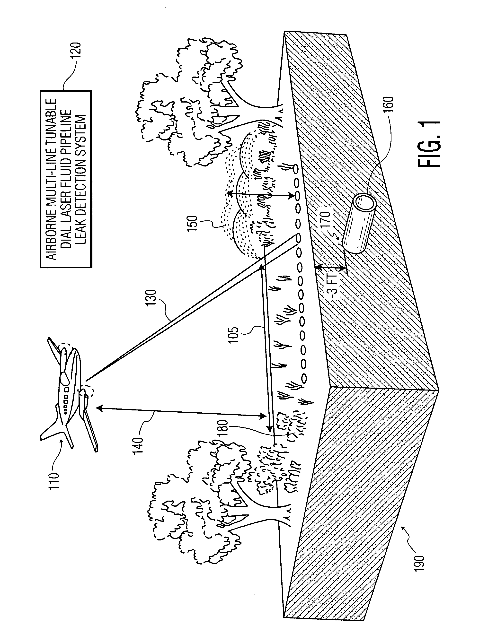
In detecting failures of gas and oil pipelines there is a particular problem, as the gas or oil pipeline is typically buried beneath ground level.
In such cases, it is difficult to make a direct visual assessment of any failures in the pipeline.
Typically, failures in pipelines are currently determined by having personnel walk the pipeline, on a periodic and costly basis, with some means to detect the trace emanating from the pipeline.

Method used


Image

  • Multi-line tunable laser system
  • Multi-line tunable laser system
  • Multi-line tunable laser system

Examples


case 1

oss sections of other targets at the predetermined ON-line and OFF-line wavelengths for a selected target are zeros: xi=12⁢ln⁢P⁡(λon_line,i)Pt⁡(λon_line,i)P⁡(λon_line,i)Pt⁡(λon_line,i)=≅(σon,i-σoff,i)⁢CPL

case 2

oss sections of other targets at the predetermined ON-line and OFF-line wavelengths for a selected target are not zeros: xi=12⁢ln⁢P⁢(λon_line,i)Pt⁢(λon_line,i)P⁢(λon_line,i)Pt⁢(λon_line,i)=≅∑l=1n⁢ ⁢(σon_line,il-σoff_line,il)⁢CPLl

where i stands for the ith wavelength, l for the lth material and CPLl for concentration path length for material l, respectively. Then in an M dimensional space X=[x1x2……xM]=Σ*CPLX_=[x1_x2_……xM_]Covariace⁢ ⁢(X)=1Q⁢∑1Q⁢(Xj-X_)⁢(Xj-X_)T

The observed signals include multiplicative and additive noise, as follows:

Y=(Multiplicative_Noise)*X+Additive_Noise

An optimal maximum likelihood estimate of CPL in multidimensional space is given by equation (12), as follows:

CPL={ΣT[COV(X)]−1Σ}−1ΣT[COV(X)]−1X  (12)

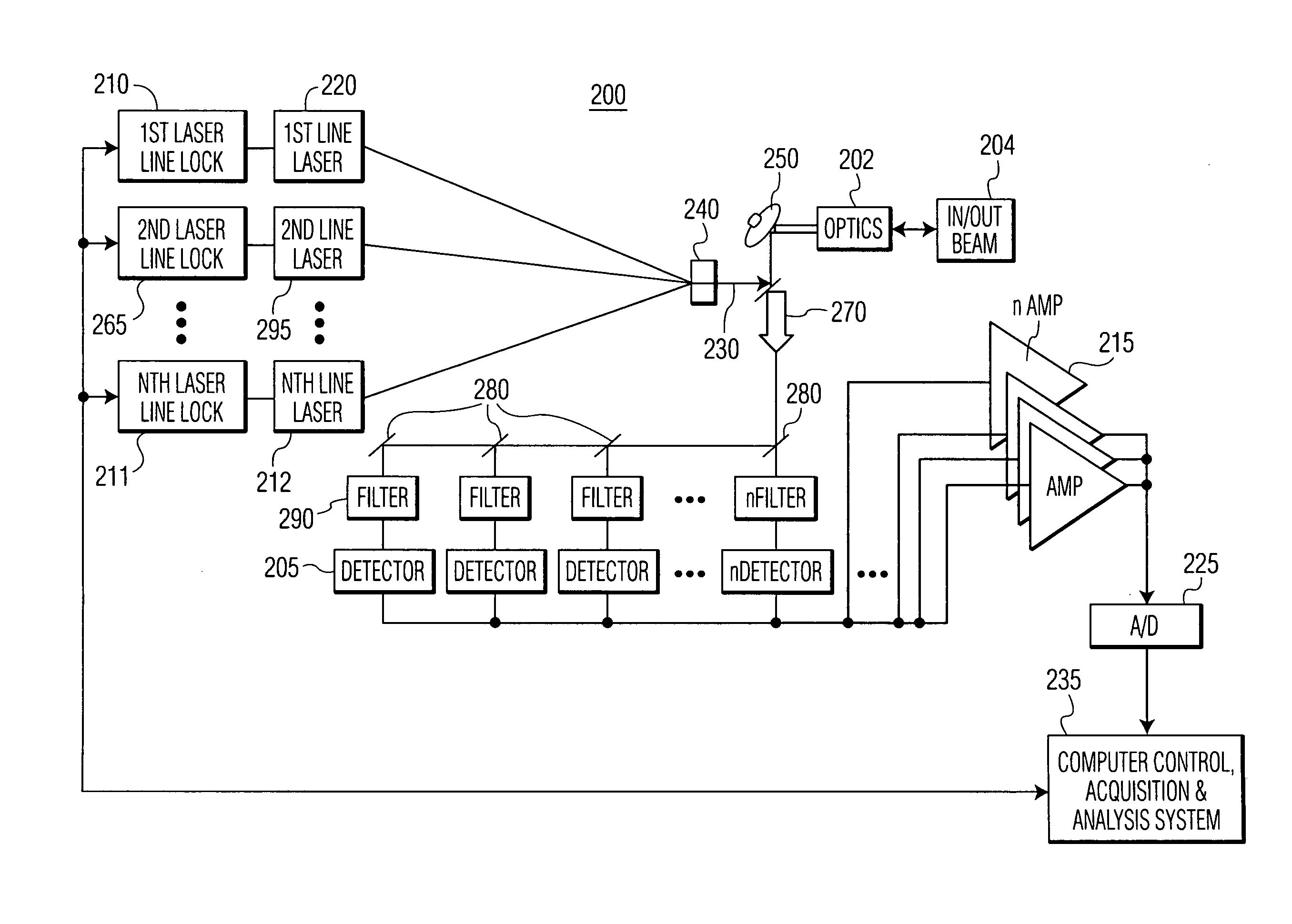
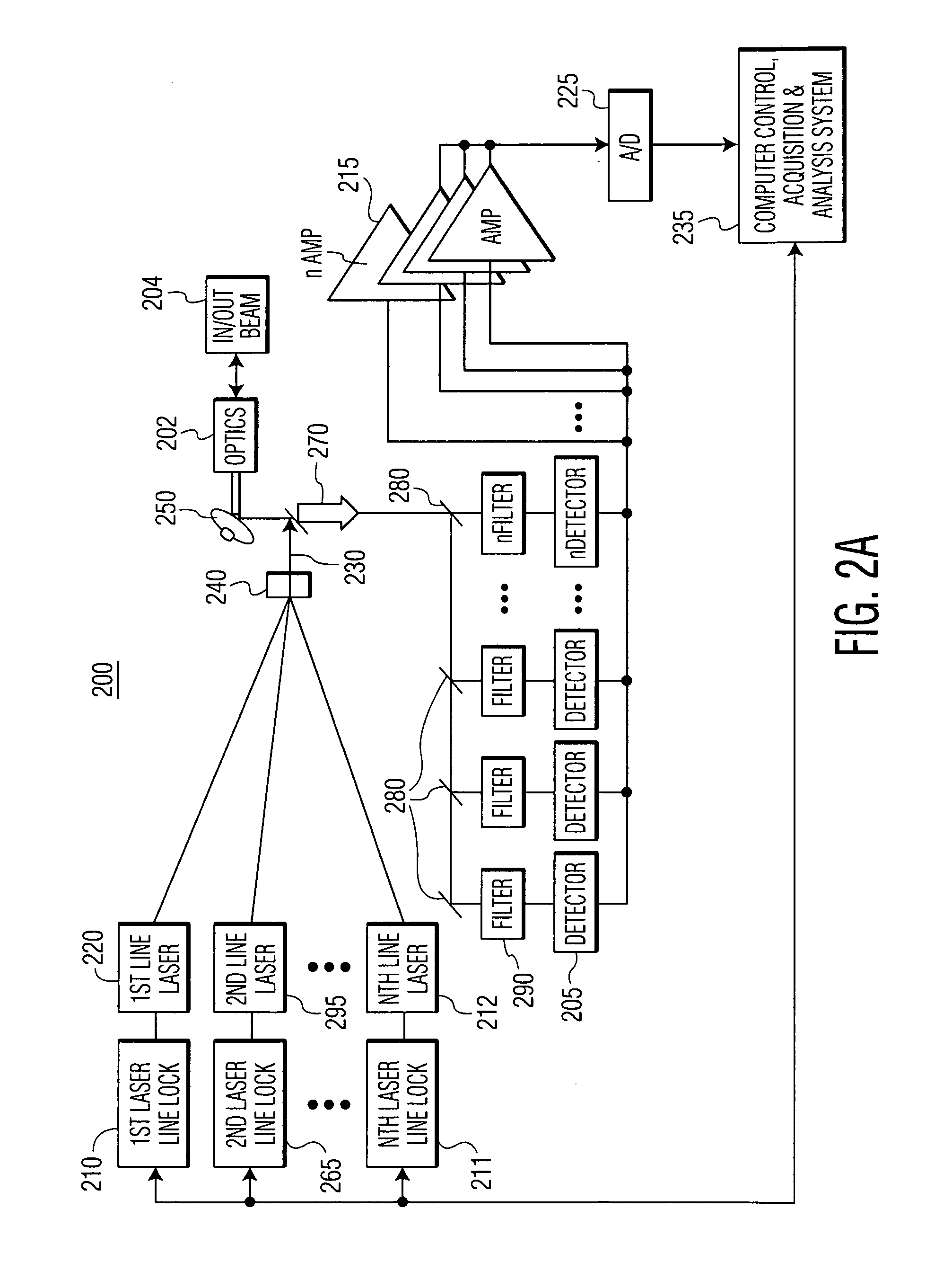
[0091] Referring next to FIG. 2A, there is shown a multi-line tunable DIAL laser system, generally designated as 200. As shown, multi-line tunable DIAL laser system 200 includes N lasers of which M are ON-line lasers and L are OFF-line lasers (N=M+L).

[0092]...


PUM


Abstract

A multi-line tunable laser system, which uses lasers as light sources to illuminate, identify and or quantify one or more targets based on multi-dimensional spectral characteristics of each target. The system includes a plurality of laser sources, each tunable to emit an electromagnetic wave, and at least one tuning controller for tuning and locking each beam of light to a wavelength of required spectral line-width. The system also includes a transmitter for transmitting each beam of light to illuminate one or more targets, and a receiver for receiving light returning from the targets and converting the returned light to electrical signals for identifying and or quantifying the targets. The system further includes N tunable lasers where, M of the N lasers are each tuned to a wavelength that is partially absorbed by the targets, and L of the N (one or more) of the lasers are each tuned to a wavelength that is absorption-free of the targets.

Description

BACKGROUND OF THE INVENTION [0001] Surveillance of ground topography is well known in the art. In ground surveillance, it is highly desirable to detect whether there has been a material failure in a man-made object such as a road, a pipeline, an electrical grid, or another man-made structure of practical interest. When a structural failure is detected, proper authorities make a determination whether remedial action is necessary. Often times a land-based crew conducts a visual inspection of the ground topography to determine if there is a material failure by traversing an area by vehicle or foot. It is frequently the case that an aircraft or a satellite includes an image capture device such as a charge coupled device (CCD), complementary metal oxide semiconductor device (CMOS) or a radiation detector, such as an infrared sensitive detector. It is well known that airborne photographic systems can also be used for capturing images of adjacent areas of the ground. [0002] When electromag...

Claims


Application Information

Patent Timeline
IPC IPC(8): H01S3/10
CPCG01N21/3504G01N2021/394G01N21/39
Inventor KALAYEH, HOOSHMAND M.
Owner HARRIS CORP
Learn More