
Eliminating mechanical spring with magnetic forces

a technology of magnetic force and mechanical spring, applied in the direction of cathode-ray tube indicators, instruments, electric digital data processing, etc., can solve the problems of inability inability to easily slide the mouse within a relatively small area, and inability to reliably and reliably control the mouse, etc., to improve the user's ability to smoothly and precisely navigate the cursor on the screen. smooth

Inactive Publication Date: 2006-11-30
AVAGO TECH ECBU IP (SINGAPORE) PTE LTD
View PDF7 Cites 41 Cited by
  • Summary
  • Abstract
  • Description
  • Claims
  • Application Information

AI Technical Summary

Benefits of technology

[0007] Using magnetic force instead of springs to center a puck in a pointing device not only improves reliability but also provides a smoother feel to the user, thereby enhancing the user's ability to smoothly and precisely navigate the cursor on the screen.

Problems solved by technology

A problem associated with pointing devices relates to re-centering the device.
In the case of a mouse, a user can only conveniently slide the mouse within a relatively small area on the user's desk or other work surface.
Although the above-described puck-based pointing device is easy to use and provides many advantages over prior pointing devices, springs are inherently subject to wear, accumulation of dirt, and associated reliability problems.

Method used


Image

  • Eliminating mechanical spring with magnetic forces
  • Eliminating mechanical spring with magnetic forces
  • Eliminating mechanical spring with magnetic forces

Examples


Embodiment Construction

[0016] In the following description, like reference numerals indicate like components to enhance the understanding of the invention through the description of the drawings. Also, although specific features, configurations, arrangements and steps are discussed below, it should be understood that such specificity is for illustrative purposes only. A person skilled in the relevant art will recognize that other features, configurations, arrangements and steps are useful without departing from the spirit and scope of the invention.

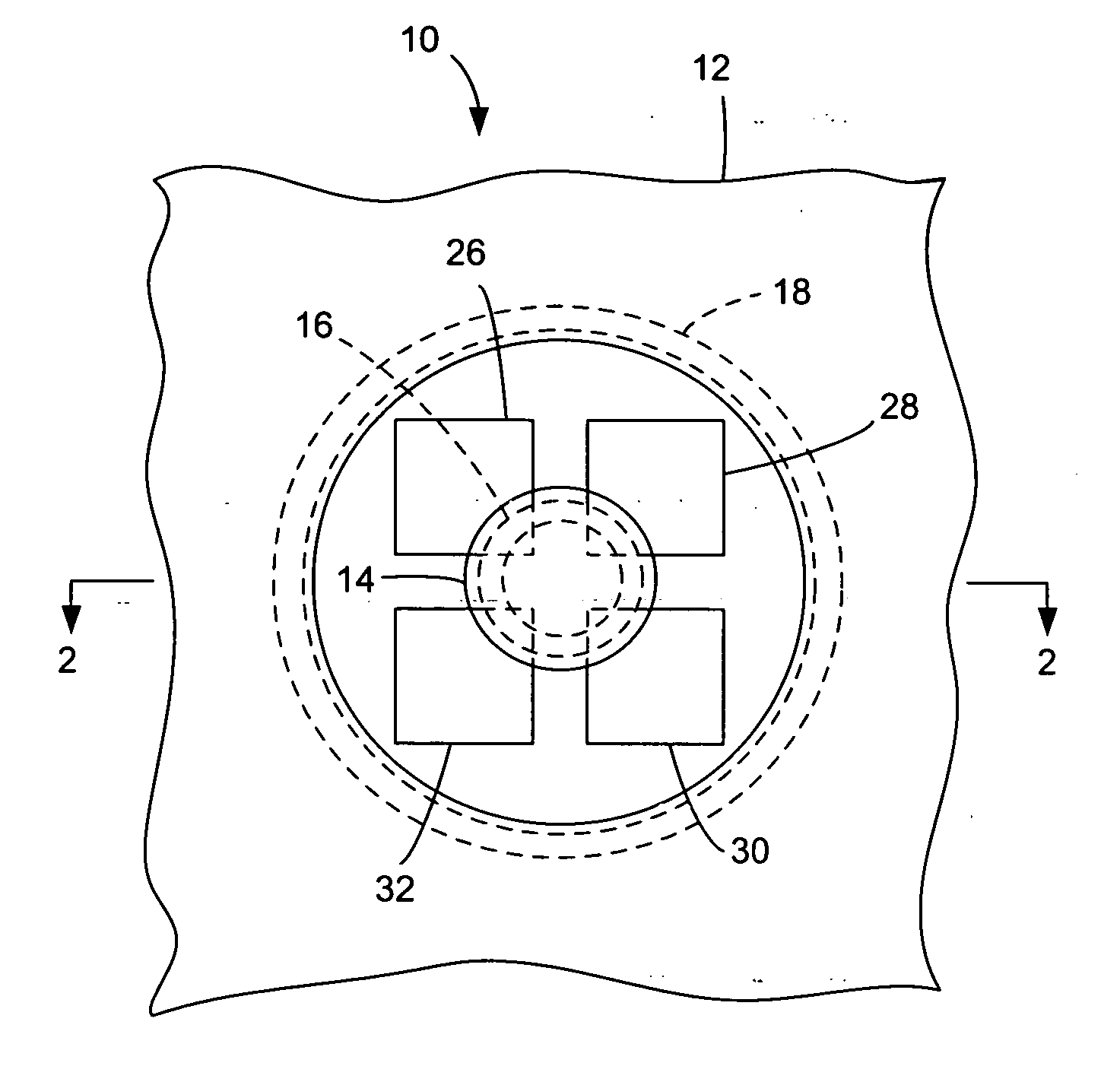
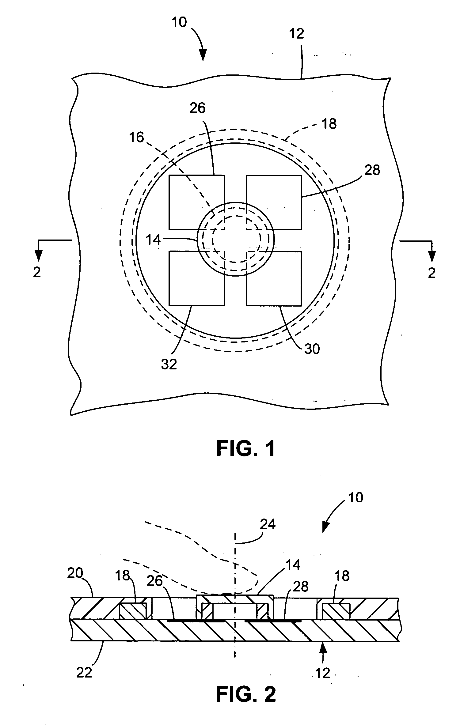
[0017] As illustrated in FIG. 1, a pointing device 10 in accordance with an exemplary embodiment of the invention includes a base 12, a puck 14, a first magnet system 16, and a second magnet system 18. Base 12 can be part of the case or other sub-assembly of a host device, such as a laptop computer, personal digital assistant (PDA), cellular telephone, or hybrid thereof, or it can be a separate element. In the exemplary embodiment, base 12 has a lower portion ...


PUM


Abstract

Magnetic force is used to re-center a puck in a pointing device or similar transducer-based device. A user can apply finger pressure to move the puck laterally away from the central position. The puck has a first magnet system, and the base of the device has a second magnet system. The magnetic repulsion or other magnetic interaction returns the puck to a central position when the user removes the finger pressure.

Description

DESCRIPTION OF THE RELATED ART [0001] Electromechanical transducer-based mechanisms can be found in a wide array of products, ranging from accelerometer systems to user input devices or controls for computers, games and machines. One such class of user input device is that which includes the computer mouse, joystick and other such pointing devices that are used to input directional or positional information. In computers, personal digital assistants, and similar equipment, a person commonly uses such a pointing device to position a cursor on a screen. [0002] A problem associated with pointing devices relates to re-centering the device. In the case of a mouse, a user can only conveniently slide the mouse within a relatively small area on the user's desk or other work surface. If the user slides the mouse a distance that brings it to the boundary of this area, the user generally lifts the mouse and sets it down again more centrally within the area in preparation for using it again in ...

Claims


Application Information

Patent Timeline
Patent Type & Authority Applications(United States)
IPC IPC(8): G09G5/08
CPCG06F3/03548
Inventor TAI, LI CHONGCHEAH, CHIANG SUNLEE, HUN KWANG
Owner AVAGO TECH ECBU IP (SINGAPORE) PTE LTD
Learn More