
High-brightness LED with protective function of electrostatic discharge damage

Inactive Publication Date: 2006-11-30
SAMSUNG ELECTRO MECHANICS CO LTD
View PDF6 Cites 84 Cited by
  • Summary
  • Abstract
  • Description
  • Claims
  • Application Information

AI Technical Summary

Benefits of technology

[0018] An advantage of the present invention is that it provides a high-brightness LED with a protective function of electrostatic discharge damage in which an LED chip and Zener diode are connected in parallel to each other through a wire on a lead frame, the Zener diode being mounted on the rear surface of the lead frame having the LED chip formed thereon, so that the light emitting diode can be protected from an electrostatic discharge damage and the brightness of the light emitting diode can be enhanced.
[0019] Additional aspects and advantages of the present general inventive concept will be set forth in part in the description which follows and, in part, will be obvious from the description, or may be learned by practice of the general inventive concept.
[0020] According to an aspect of the invention, a high-brightness LED with a protective function of electrostatic discharge damage includes a lead frame that is formed with a pair of anode and cathode leads; a package that is formed of synthetic resin and in which a portion of the lead frame is housed; an LED chip that is mounted on the upper surface of the lead frame inside the package; an electrostatic discharge damage protecting element that is mounted on the lower surface of the lead frame inside the package and is connected parallel to the LED chip through a wire; and a molding material that is filled in the package so as to protect the LED chip.
[0021] According to another aspect of the invention, the LED chip is mounted on the upper surface of the anode lead of the lead frame, and the electrostatic discharge damage protecting element is mounted on the lower surface of the cathode lead of the lead frame.
[0022] According to a further aspect of the invention, the LED chip is mounted on the upper surface of the cathode lead of the lead frame, and the electrostatic discharge damage protecting element is mounted on the lower surface of the anode lead of the lead frame.
[0023] According to a still further aspect of the invention, the LED chip is mounted on the upper surface of the anode lead of the lead frame, and the electrostatic discharge damage protecting element is mounted on the lower surface of the anode lead of the lead frame.

Problems solved by technology

Therefore, the lead frame should be large enough in order to secure a sufficient region for wire-bonding, and thus the size of the package of the light emitting diode becomes large, which makes it difficult to miniaturize the package of the light emitting diode.
Further, if the Zener diode and the LED chip are mounted in parallel on the lead frame, light emitted from the LED chip is absorbed or diffused by the Zener diode, thereby reducing the brightness of the light emitting diode.
Further, the characteristic and reliability of the light emitting diode are deteriorated, and light emission efficiency is also reduced.

Method used


Image

  • High-brightness LED with protective function of electrostatic discharge damage
  • High-brightness LED with protective function of electrostatic discharge damage
  • High-brightness LED with protective function of electrostatic discharge damage

Examples


first embodiment

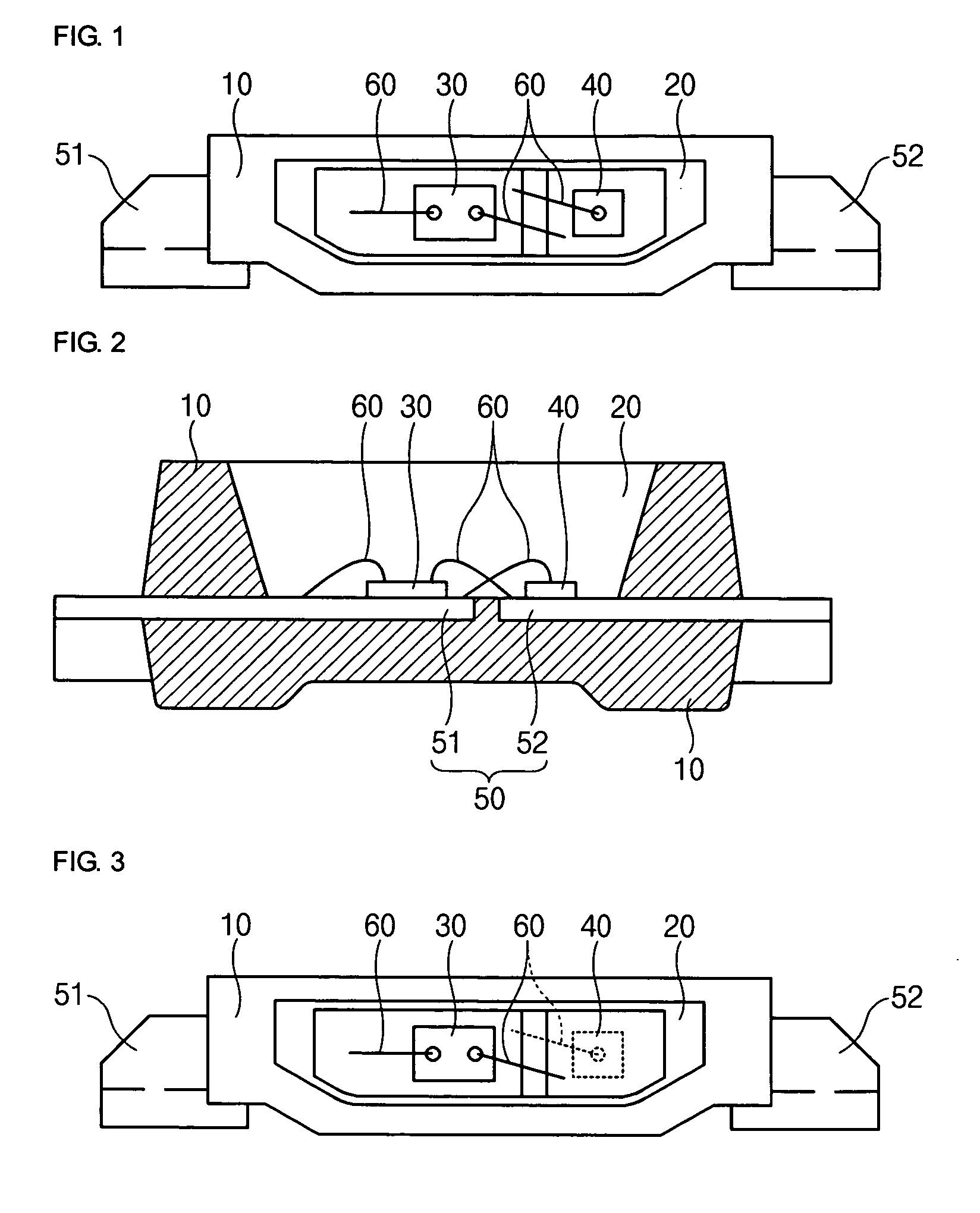
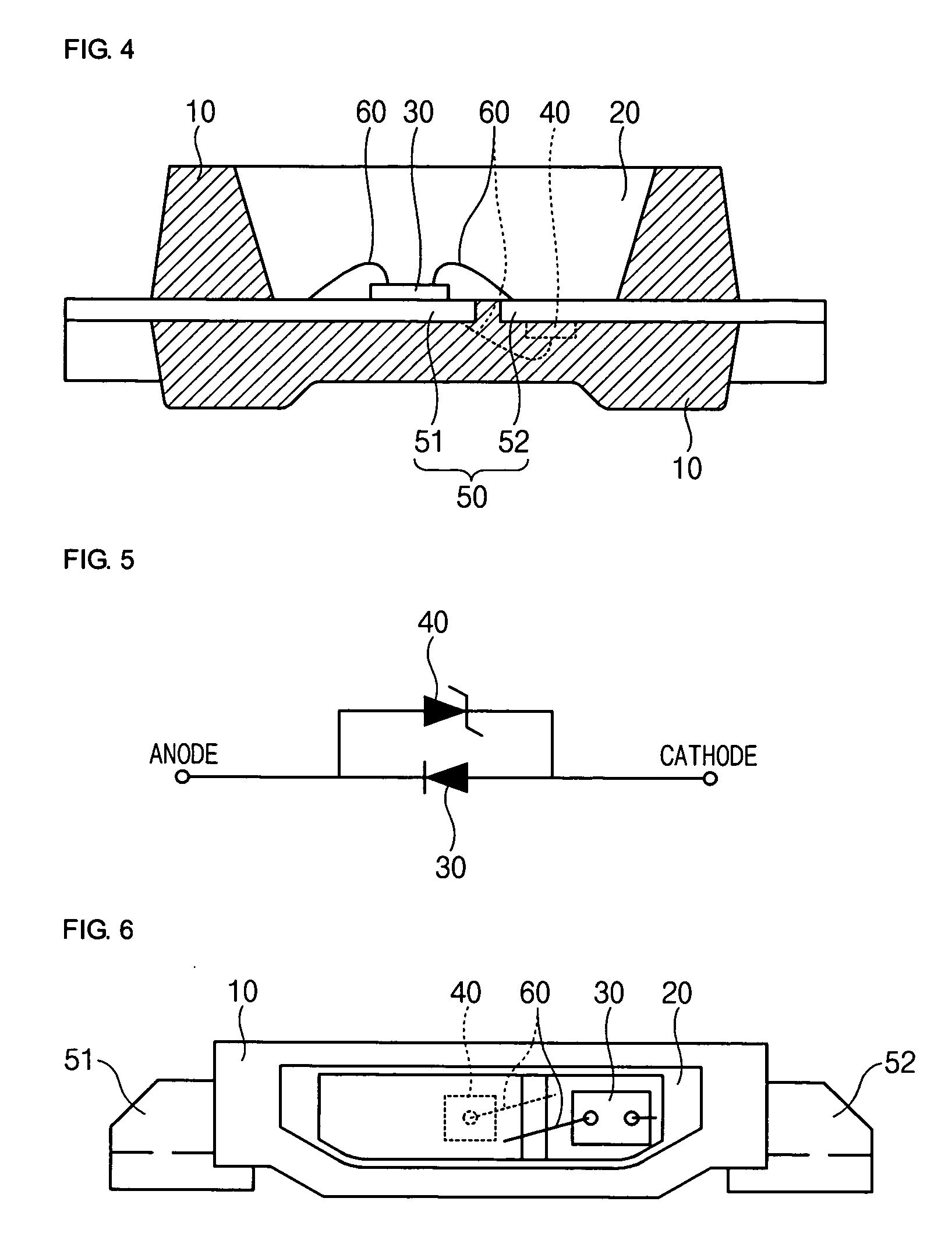
[0042] Referring to FIGS. 3 to 5, a high-brightness LED with a protective function of electrostatic discharge damage according to a first embodiment of the invention will be described in detail.

[0043]FIG. 3 is a front view illustrating the high-brightness LED with a protective function of electrostatic discharge damage according to the first embodiment of the invention. FIG. 4 is a plan cross-sectional view illustrating the high-brightness LED with a protective function of electrostatic discharge damage shown in FIG. 3. FIG. 5 is a diagram schematically showing a reverse current preventing circuit of the high-brightness LED with a protective function of electrostatic discharge damage shown in FIG. 3.

[0044] As shown in FIGS. 3 to 5, the high-brightness LED with a protective function of electrostatic discharge damage according to the first embodiment of the invention is mounted on a printed circuit board (not shown) or the like through a lead frame 50 projecting from a package 10 fo...

second embodiment

[0053] Referring to FIGS. 6 and 7, a second embodiment of the invention will be described. Here, the descriptions of the same components of the second embodiment as those of the first embodiment will be omitted. Only different components will be described.

[0054]FIG. 6 is a front view illustrating a high-brightness LED with a protective function of electrostatic discharge damage according to the second embodiment of the invention. FIG. 7 is a plan cross-sectional view illustrating the high-brightness LED with a protective function of electrostatic discharge damage shown in FIG. 6.

[0055] The high-brightness LED with a protective function of electrostatic discharge damage according to the second embodiment has almost the same construction as the high-brightness LED with a protective function of electrostatic discharge damage according to the first embodiment. As shown in FIGS. 6 and 7, however, the LED chip 30 is mounted on the upper surface of the anode lead 52, and the electrostati...

third embodiment

[0057] Referring to FIGS. 8 and 9, a third embodiment of the invention will be described. Since most components of the third embodiment are the same as those of the first embodiment, only a different construction will be described.

[0058]FIG. 8 is a front view illustrating a high-brightness LED with a protective function of electrostatic discharge damage according to the third embodiment of the invention. FIG. 9 is a plan cross-sectional view illustrating the high-brightness LED with a protective function of electrostatic discharge damage shown in FIG. 8.

[0059] As shown in FIGS. 8 and 9, even in the high-brightness LED according to the third embodiment, the LED chip 30 and the electrostatic discharge damage protecting element 40 are connected parallel to each other and are simultaneously present up and down with reference to the lead frame 50. Therefore, the third embodiment can obtain the same operation and effect as those of the first and second embodiments.

[0060] In the high-br...


PUM


Abstract

The present invention relates to a high-brightness LED with a protective function of electrostatic discharge damage. The high-brightness LED with a protective function of electrostatic discharge damage includes a lead frame that is formed with a pair of anode and cathode leads; a package that is formed of synthetic resin and in which a portion of the lead frame is housed; an LED chip that is mounted on the upper surface of the lead frame inside the package; an electrostatic discharge damage protecting element that is mounted on the lower surface of the lead frame inside the package and is connected parallel to the LED chip through a wire; and a molding material that is filled in the package so as to protect the LED chip.

Description

CROSS-REFERENCE TO RELATED APPLICATIONS [0001] The application claims the benefit of Korea Patent Application No. 2005-0046283 filed with the Korea Industrial Property Office on May 31, 2005, the disclosure of which is incorporated herein by reference. BACKGROUND OF THE INVENTION [0002] 1. Field of the Invention [0003] The present invention relates to a high-brightness LED with a protective function of electrostatic discharge damage, and more specifically, a high-brightness LED with a protective function of electrostatic discharge damage which not only protects a light emitting diode from electrostatic discharge damage, but also enhances the brightness of the light emitting diode. [0004] 2. Description of the Related Art [0005] In general, a light emitting diode (LED) generates minority carriers (electrons or holes) injected by using the p-n junction structure of a semiconductor, and recombines the minority carriers so as to emit light. In other words, if a forward voltage is applie...

Claims


Application Information

Patent Timeline
IPC IPC(8): H01L33/00H01L33/52H01L33/62
CPCH01L25/167H01L33/486H01L2224/48091H01L2224/48247H01L2924/12032H01L2924/00014H01L2924/00
Inventor BAEK, JONG HWANPARK, JE MYUNGRYO, GEUN CHANGKIM, CHANG WOOKSEO, JUN HOSONG, YOUNG JAE
Owner SAMSUNG ELECTRO MECHANICS CO LTD
Learn More